Lens focusing device

A focusing device and lens technology, which is applied in the field of cameras, can solve problems such as jamming, unbalanced matching accuracy of parts, and failure to meet the accuracy requirements of the optical system, so as to achieve the effect of ensuring accuracy and solving the unbalanced matching accuracy

Pending Publication Date: 2020-03-17
DONGGUAN YUTONG OPTICAL TECH
View PDF0 Cites 1 Cited by
  • Summary
  • Abstract
  • Description
  • Claims
  • Application Information

AI Technical Summary

Problems solved by technology

[0002] With the maturity of the lens industry and the improvement of security awareness of the general public, the requirements for security lenses in the market are also getting higher and higher. From the initial VGA (Video Graphics Array, that is, Video Graphics Array) to the current 4K lens, The image surface has also evolved from the largest 1 / 4" to the current 1 / 1.8" or even larger. This evolution has undoubtedly added a lot of difficulty to the design of the optical system. The dual requirements of high pixels and large image surface lower, resulting in lens back focus sensitivity and shortened back focus length
As far as the issue of back focus sensitivity is concerned, the traditional operation of connecting the thread to the base and manually rotating the lens to focus can no longer meet the precision requirements of the optical system, so it is necessary to use a high-precision auto-focus module to achieve focus
[0003] The traditional auto-focus module uses a gearbox system to achieve the purpose of self-focusing. However, although the gearbox system has high focusing accuracy, its structure always has a certain amount of draft due to the existing mold production. The inclination causes the automatic focus module to have a certain gap in the position of the mechanical dead point at both ends, and the matching accuracy between the parts cannot be balanced. Often, the bottom can fit but the end gap is too large, resulting in problems such as shaking; or The end fits well but the bottom fits tight, resulting in stuck and serious out-of-step problems

Method used


Image

  • Lens focusing device
  • Lens focusing device
  • Lens focusing device

Examples


Embodiment Construction

[0032] In order to facilitate the understanding of the present invention, the present invention will be described more fully below with reference to the associated drawings. Preferred embodiments of the invention are shown in the accompanying drawings. However, the present invention can be embodied in many different forms and is not limited to the embodiments described herein. On the contrary, these embodiments are provided to make the understanding of the disclosure of the present invention more thorough and comprehensive.

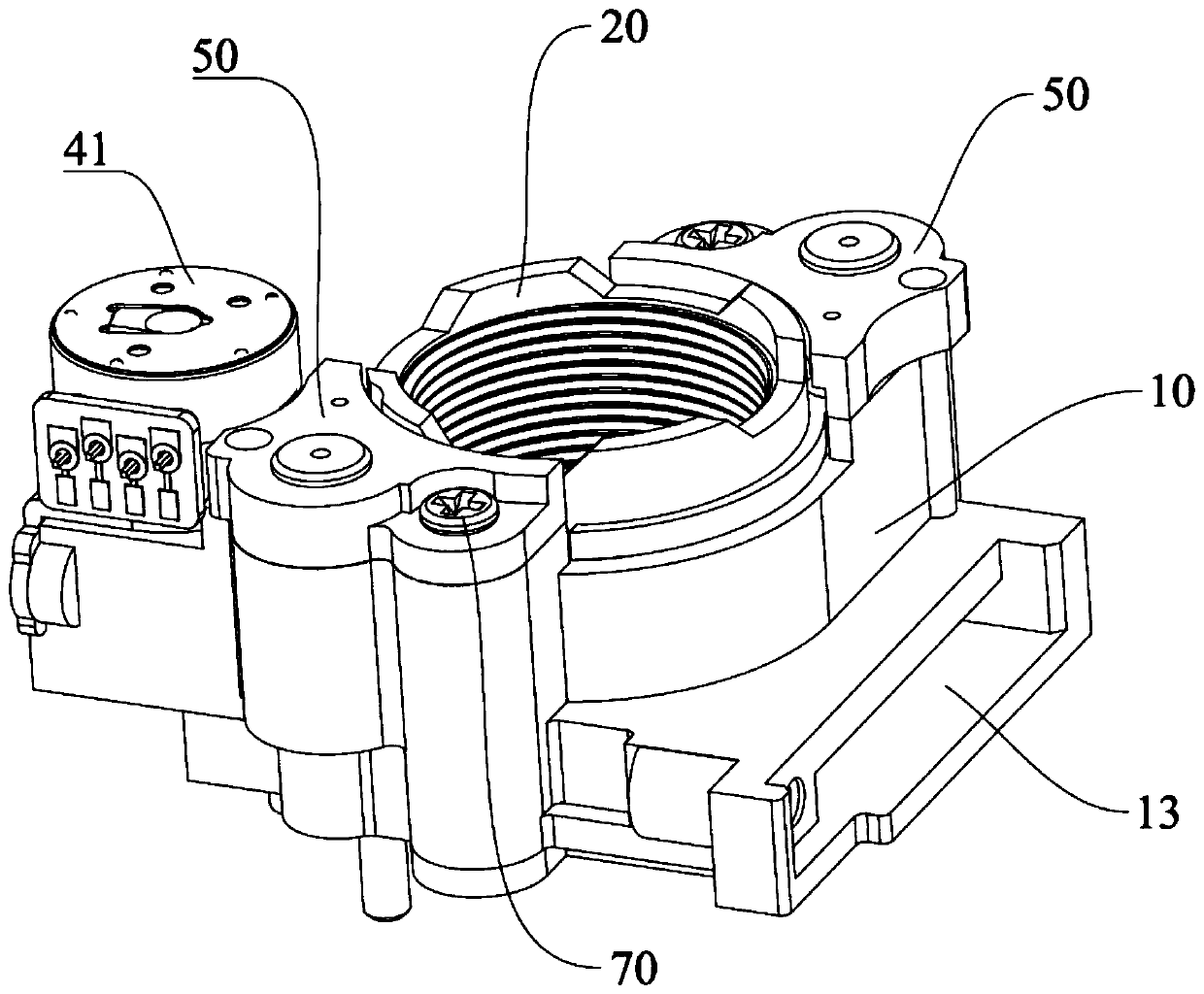
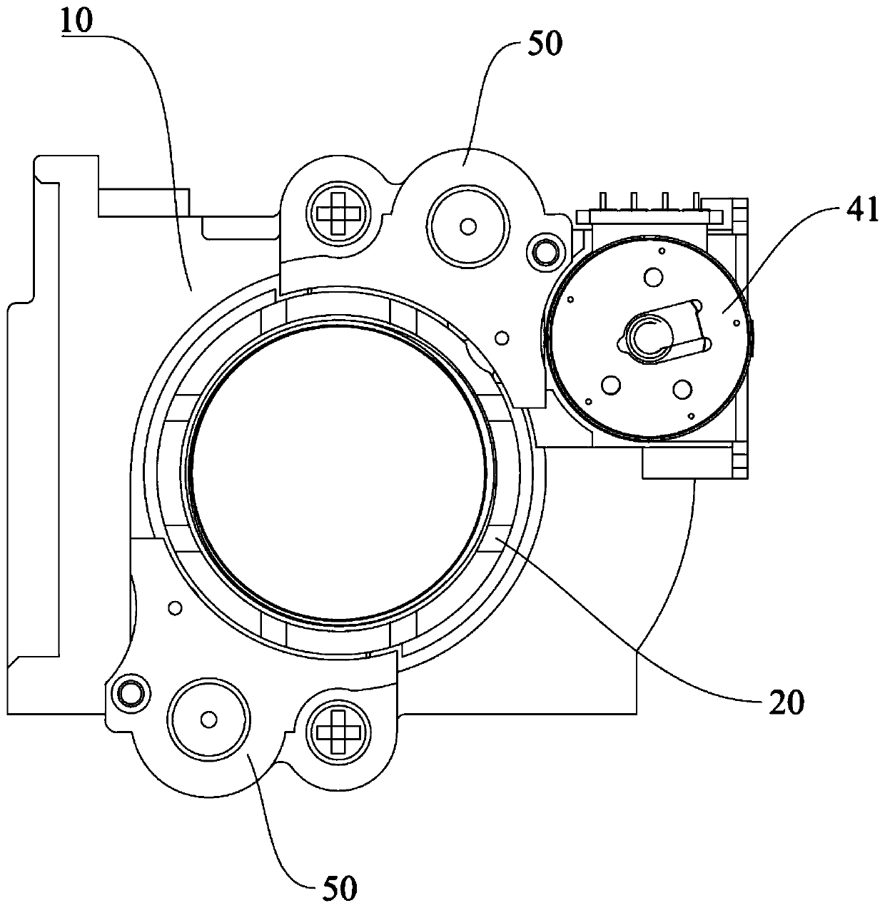
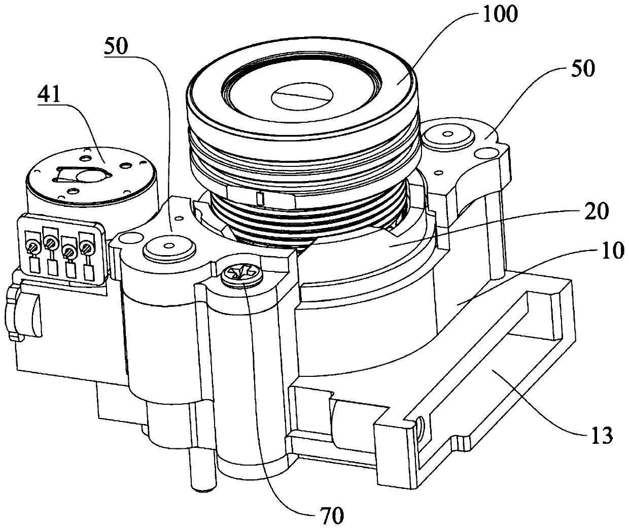
[0033] This embodiment provides a lens focusing device, such as Figure 1 to Figure 9 As shown, the lens focusing device includes a base 10, a lens connecting base 20, a guide shaft 30 and a motor 41, wherein the lens connecting base 20 is used to connect the lens 100, and the lens connecting base 20 is movably arranged on the base 10; the guiding shaft 30 is used for positioning the lens connector 20 and guiding the movement of the lens connector 20. T...


PUM


Abstract

The invention discloses a lens focusing device. The lens focusing device comprises a base; a lens connecting base which is movably arranged on the base; a guide shaft which is arranged in the lens connecting base in a penetrating manner, and one end of which is connected with the base; and a motor which is arranged on the base. The output end of the motor is connected with a lead screw and can drive the lead screw to rotate, the length direction of the lead screw being the same as that of the guide shaft; the lead screw is sleeved by a connecting piece; the connecting piece is connected with the lens connecting base; and the connecting piece can do reciprocating motion in the length direction of the lead screw along with rotation of the lead screw so as to drive the lens connecting base todo reciprocating motion in the length direction of the guide shaft. The lens connecting base can be driven to reciprocate in the length direction of the guide shaft by controlling the motor to rotateforwards and backwards, and thus the purpose of automatic focusing is achieved; and the lens connecting base is only matched with the guide shaft, and the matching surface between products is small,so that the precision is easier to guarantee on the mold, and the problem that the matching precision between parts of a self-focusing module of a traditional gearbox cannot be balanced is solved.

Description

technical field [0001] The invention relates to the technical field of cameras, in particular to a lens focusing device. Background technique [0002] With the maturity of the lens industry and the improvement of security awareness of the general public, the requirements for security lenses in the market are also getting higher and higher. From the initial VGA (Video Graphics Array, that is, Video Graphics Array) to the current 4K lens, The image surface has also evolved from the largest 1 / 4" to the current 1 / 1.8" or even larger. This evolution has undoubtedly added a lot of difficulty to the design of the optical system. The dual requirements of high pixels and large image surface If the lens is lowered, the back focus of the lens is sensitive and the length of the back focus is shortened. As far as the issue of back focus sensitivity is concerned, the traditional operation of connecting the screw to the base and manually rotating the lens to focus can no longer meet the a...

Claims


Application Information

Patent Timeline
Patent Type & Authority Applications(China)
IPC IPC(8): G02B7/09G02B7/10G03B13/36
CPCG02B7/09G02B7/10G03B13/36
Inventor 毛才荧刘丽花
Owner DONGGUAN YUTONG OPTICAL TECH
Why Eureka
Try Eureka