
Drainage system of water heater

A drainage system and water heater technology, applied in fluid heaters, lighting and heating equipment, etc., can solve the problems of waste of cold water, inability to drain, inconvenient use, etc.

Active Publication Date: 2020-03-20
ZHENJIANG BODE ELECTRIC EQUIP CO LTD
View PDF6 Cites 0 Cited by
  • Summary
  • Abstract
  • Description
  • Claims
  • Application Information

AI Technical Summary

Problems solved by technology

[0002] In the current water heater pipeline laying, since the water mixing valve is far away from the water outlet of the water heater, the hot water in the hot water pipe cannot be discharged after the water mixing valve is closed in winter. Release the water from the hot water pipe first, which is extremely inconvenient to use, and will cause the cold water in the cold water pipe and the hot water pipe to be wasted

Method used


Image

  • Drainage system of water heater
  • Drainage system of water heater
  • Drainage system of water heater

Examples


Embodiment Construction

[0040] The technical solution of the present invention is further described below, but the scope of protection is not limited to the description.

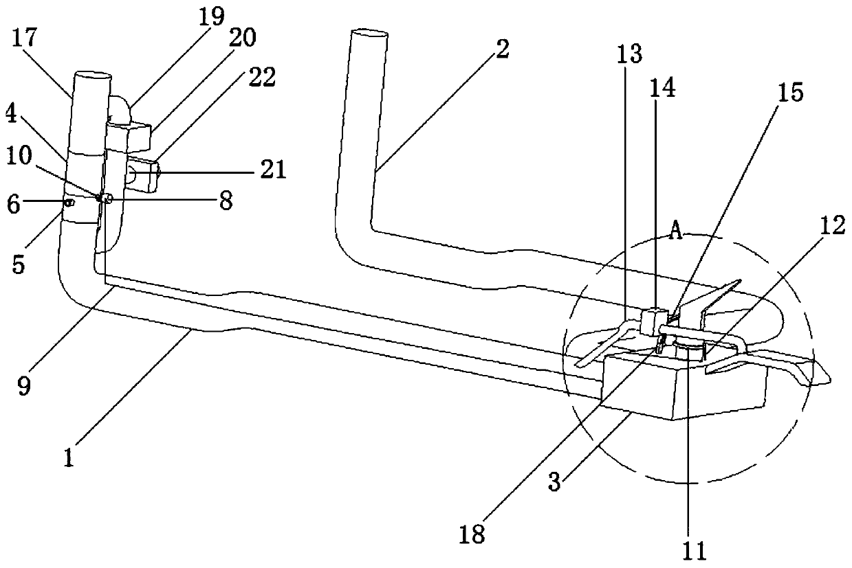
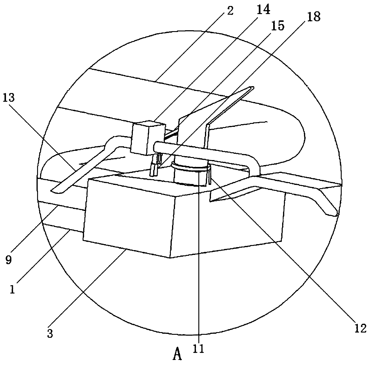
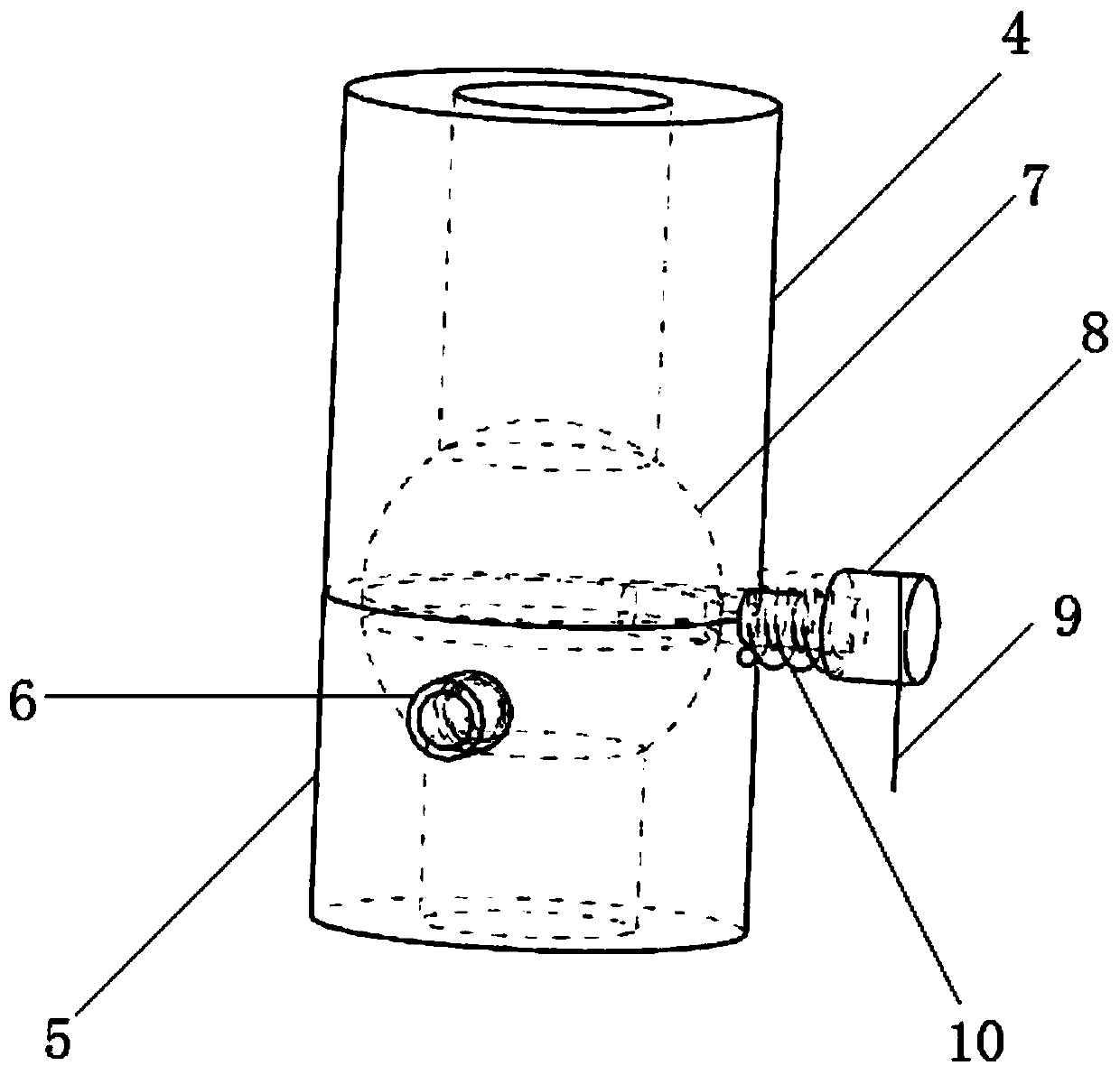
[0041] see Figure 1 to Figure 7 .

[0042] A drainage system for a water heater according to the present invention comprises a hot water pipe A1, a cold water pipe 2, and a water mixing valve 3, and one head of the hot water pipe A1 and the cold water pipe 2 is respectively connected to the hot water port and the cold water port of the water mixing valve 3 in airtight and fixed communication;

[0043] Among them, also include:

[0044] Joint pipe A4, joint pipe B5, hot water pipe B17, joint pipe A4 and joint pipe B5 are sealed and fixedly connected, the inner surface of joint pipe A4 and joint pipe B5 is a hemispherical surface, the upper end of joint pipe A4 is airtightly connected with hot water pipe B17, and the joint The lower end of the pipe B5 is airtightly connected with the hot water pipe A1;

[0045] The intake pipe 6 ...


PUM


Abstract

The invention discloses a drainage system of a heat water. The drainage system comprises a hot water pipe A, a cold water pipe and a water mixing valve and one end of the hot water pipe A and one endof the cold water pipe are fixedly communicated with a hot water port and a cold water port of the water mixing valve respectively; the system further comprises a connector pipe A, a connector pipe B,a hot water pipe B, an air inlet pipe, a reversing ball block, a rotating column inhaul cable, a torsional spring, a bearing and a water distribution pipe; an inner line, connected with an adjustinghandle of the water mixing valve, of the inhaul cable retracts, the inner line end, connected with a rotating column, of the inhaul cable rotates together with the rotating column to reset under effect of the torsional spring; and at the moment, the reversing ball block rotates from the position of blocking the air inlet pipe to the position of blocking the hot water pipe A, hot water in an electric heating water tank cannot enter the hot water pipe A again, external air enters the air inlet pipe to continuously press down the hot water in the hot water pipe A, and the hot water in the hot water pipe A is discharged from the water distribution pipe. Thus, the problem that the hot water in the hot water pipe cannot be discharged after the water mixing valve is closed in winter at present issolved.

Description

technical field [0001] The invention belongs to the technical field of hot water pipes, and relates to a water heater drainage system. Background technique [0002] In the current water heater pipeline laying, since the water mixing valve is far away from the water outlet of the water heater, the hot water in the hot water pipe cannot be discharged after the water mixing valve is closed in winter. The water in the hot water pipe is released earlier, which is extremely inconvenient to use, and will cause the cold water in the cold water pipe and the hot water pipe to be wasted simultaneously. Contents of the invention [0003] In order to solve the above technical problems, the present invention provides a water heater drainage system. [0004] The present invention is achieved through the following technical solutions. [0005] A drainage system for a water heater provided by the present invention comprises a hot water pipe A, a cold water pipe, and a water mixing valve,...

Claims


Application Information

Patent Timeline
Patent Type & Authority Applications(China)
IPC IPC(8): F24H9/16F24H9/14
CPCF24H9/144F24H9/16
Inventor 胡焰郑鹏黄梅爱何丹马凤张婉
Owner ZHENJIANG BODE ELECTRIC EQUIP CO LTD
Learn More