This helps you quickly interpret patents by identifying the three key elements:
Problems solved by technology
Method used
Benefits of technology
Problems solved by technology
[0003] Patent No. 201711390939.3 discloses a planar transformer. The planar transformer is the primary type, in which the shielding winding has one turn and the auxiliary winding has three turns. The common-mode current is adjusted by adjusting the number of turns inside the compound winding, but this scheme PCB has many layers, complex process and high cost
The working voltage of the primary winding is high, and there will be a relatively large potential difference between it and the magnetic core, which may cause insulation breakdown between the magnetic core and the winding, and reduce the reliability of the product.
Method used
Image
Click on the blue label to locate the original text in one second.
Reading with bidirectional positioning of images and text.
Examples
Embodiment 1
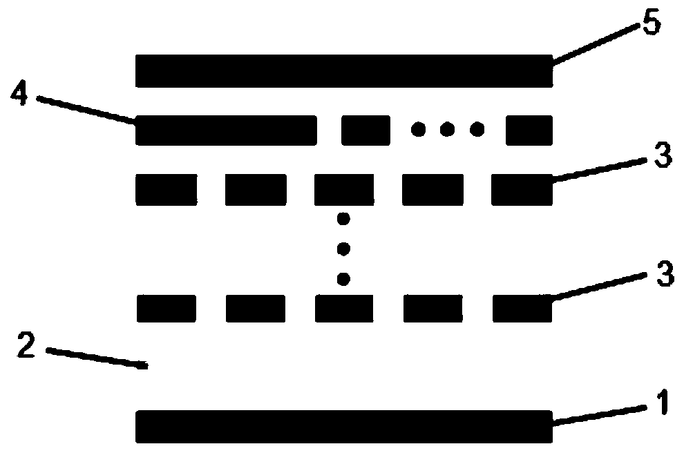
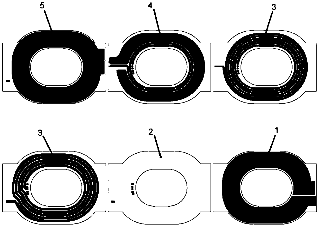
[0036] see figure 1 , this embodiment provides a planar transformer, which is a sub-primary structure. output power specifications, the top shielding layer 4 and the bottom shielding layer 2 can be connected in series or in parallel, the middle layer is between the bottom and top layer coils, the middle layer can be a multi-layer structure, and the planar transformer can have a 6-14-layer structure as a whole ,Such as figure 2 It is a schematic diagram of the 6-layer structure.
[0037] The bottom-level coil 1 starts from the secondary static point potential and is wound clockwise or counterclockwise; the winding direction of the top-level coil 5 is the same as that of the bottom-level coil 1 .
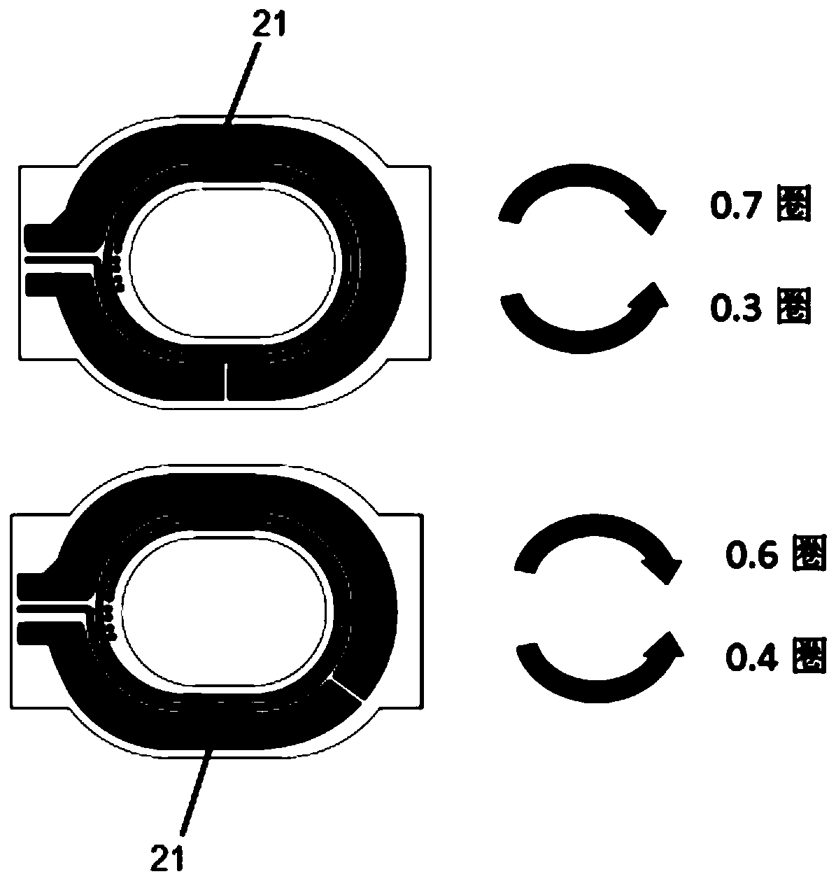
[0038] Wherein, the top shielding layer 4 and the bottom shielding layer 2 both include shielding coils 21, and at least one shielding coil 21 in the top shielding layer 4 and the bottom shielding layer 2 includes N1 clockwise coils and N2 counterclockwise coils, the The sum of N1...
Embodiment 2
[0045] see Figure 6 , the present embodiment provides a planar transformer, the difference from Embodiment 1 is that the top shielding layer 4 and / or the bottom shielding layer 2 also includes a first auxiliary winding 22, and the top shielding layer 4 and / or the bottom shielding layer 2 includes N3 clockwise shielding coils 21 and N4 anticlockwise first auxiliary windings 22, N4 greater than 3, by adjusting the combination of the forward and reverse ratio of the shielding layer and the first auxiliary winding 22 and the copper platinum area of the shielding layer, the best EMI performance is achieved. According to different output specifications, the ratio can be 2 / 6 or 1.5 / 6, or other more ratios.
[0046]In this embodiment, the inner circle of the N3 clockwise shielding coil 21 is provided with N4 counterclockwise first auxiliary windings 22 , wherein N3 is greater than 1.
[0047] The area of the N3 clockwise shielding coil and the value of N3 can be changed to adjus...
Embodiment 3
[0050] This embodiment provides a planar transformer. On the basis of the first embodiment, an auxiliary winding is added to the inner circle of the shielding coil and designed on the same layer to reduce the total layer thickness and reduce the cost.
[0051] Such as Figure 7 , Figure 8 As shown, the bottom shielding layer 2 further includes a second auxiliary winding 23 , and the second auxiliary winding 23 is arranged on the inner coil of the shielding coil of the bottom shielding layer 2 .
[0052] or as figure 1 , Figure 9 As shown, the top shielding layer 4 also includes a second auxiliary winding 23 , and the second auxiliary winding 23 is arranged on the inner coil of the shielding coil of the top shielding layer 4 .
[0053] or as Figure 10 , Figure 11 As shown, both the bottom shielding layer 2 and the top shielding layer 4 include a second auxiliary winding 23 , and the second auxiliary winding 23 is arranged in the inner circle of the shielding coil of th...
PUM
Abstract
The invention discloses a planar transformer and a power converter. The planar transformer sequentially comprises a bottom-layer secondary coil, a bottom-layer shielding layer, a primary coil, a top-layer shielding layer and a top-layer secondary coil from bottom to top, each of the top shielding layer and the bottom shielding layer comprises a shielding coil; at least one shielding coil in the top shielding layer and the bottom shielding layer comprises N1 circles of clockwise coils and N2 circles of anticlockwise coils; or the top shielding layer and / or the bottom shielding layer further comprise / comprises a first auxiliary winding; the top shielding layer or the bottom shielding layer comprises N3 circles of clockwise shielding coils and N4 circles of anticlockwise first auxiliary windings, N4 is larger than 3, and the compensation common-mode current of the planar transformer is adjusted by adjusting the ratio of N1 to N2 or the ratio of N3 to N4. According to the planar transformer and the power converter provided by the invention, the common-mode current caused by the primary winding is reduced, so that the interference of EMI common-mode noise is reduced.
Description
technical field [0001] The invention relates to the technical field of transformers, in particular to a planar transformer and a power converter. Background technique [0002] The common-mode current of the transformer has a great influence on EMI. It is necessary to reduce the common-mode current caused by the primary coil as much as possible. Usually, in a traditional transformer, the common-mode current is adjusted by adjusting the number of turns of the transformer shielding winding to reduce EMI. interference from common mode noise. [0003] Patent No. 201711390939.3 discloses a planar transformer. The planar transformer is the primary type, in which the shielding winding has one turn and the auxiliary winding has three turns. The common-mode current is adjusted by adjusting the number of turns inside the compound winding, but this scheme The PCB has many layers, complex process and high cost. The working voltage of the primary winding is high, and there will be a rel...
Claims
Application Information
Patent Timeline
Application Date:The date an application was filed.
Publication Date:The date a patent or application was officially published.
First Publication Date:The earliest publication date of a patent with the same application number.
Issue Date:Publication date of the patent grant document.
PCT Entry Date:The Entry date of PCT National Phase.
Estimated Expiry Date:The statutory expiry date of a patent right according to the Patent Law, and it is the longest term of protection that the patent right can achieve without the termination of the patent right due to other reasons(Term extension factor has been taken into account ).
Invalid Date:Actual expiry date is based on effective date or publication date of legal transaction data of invalid patent.

