
Driving circuit and its control method for simulating color near-eye LCD

A liquid crystal display and drive circuit technology, applied to static indicators, instruments, etc., can solve the problems of low power consumption, small size and portability, large space size of the whole machine, complex circuit structure, etc., and reduce production costs , The effect of reducing the power consumption of the whole machine, reducing the weight and space volume

Inactive Publication Date: 2010-03-10
SHENZHEN YANGTZE LIVETECH
View PDF5 Cites 0 Cited by
  • Summary
  • Abstract
  • Description
  • Claims
  • Application Information

AI Technical Summary

Problems solved by technology

Among them, the driving circuit of the color near-eye display and its control display method are the key points. The display driving circuit of the existing analog color near-eye liquid crystal display adopts IC chips with various types of functions in order to realize more diverse and gorgeous functions. There are image decoding chips, display drive signal control chips, configuration single-chip microcomputer chips, display drive power amplifier op-amp modules, multi-power supply modules, passive configuration electronic components, etc. The circuit structure is relatively complicated, which leads to high cost of the whole system and system High power consumption and large space size of the whole machine weaken the advantages of low power consumption, small size and portability of the near-eye display

Method used


Image

  • Driving circuit and its control method for simulating color near-eye LCD
  • Driving circuit and its control method for simulating color near-eye LCD
  • Driving circuit and its control method for simulating color near-eye LCD

Examples


Embodiment Construction

[0061] In order to further understand the invention content, characteristics and effects of the present invention, the following embodiments are listed hereby, and the driving circuit and the control method thereof of the analog color near-eye liquid crystal display of the present invention are described in detail as follows:

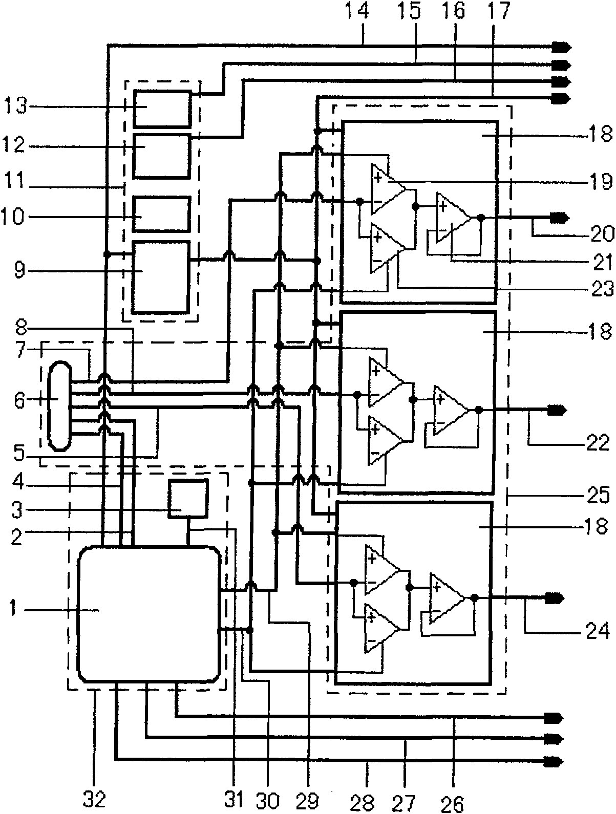
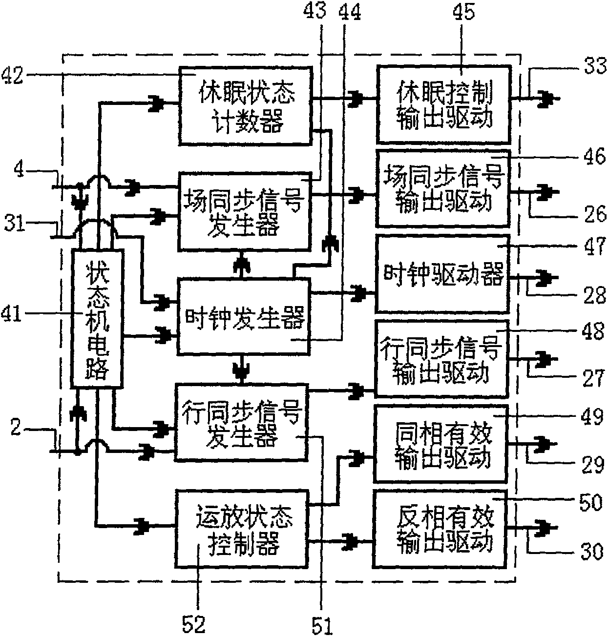
[0062] Such as figure 1 As shown, the drive circuit of the analog color near-eye liquid crystal display of the present invention includes an RGB analog signal processing circuit module 25, through the inverting operational amplifier effective signal line 29, the non-inverting operational amplifier effective signal line 30 and the RGB analog signal processing circuit module 25 connected to the digital signal processing circuit module 32, and respectively connected to the RGB analog signal processing circuit module 25 and the digital signal processing circuit module 32 to provide the required multi-potential output voltage source circuit module 11 with mor...


PUM


Abstract

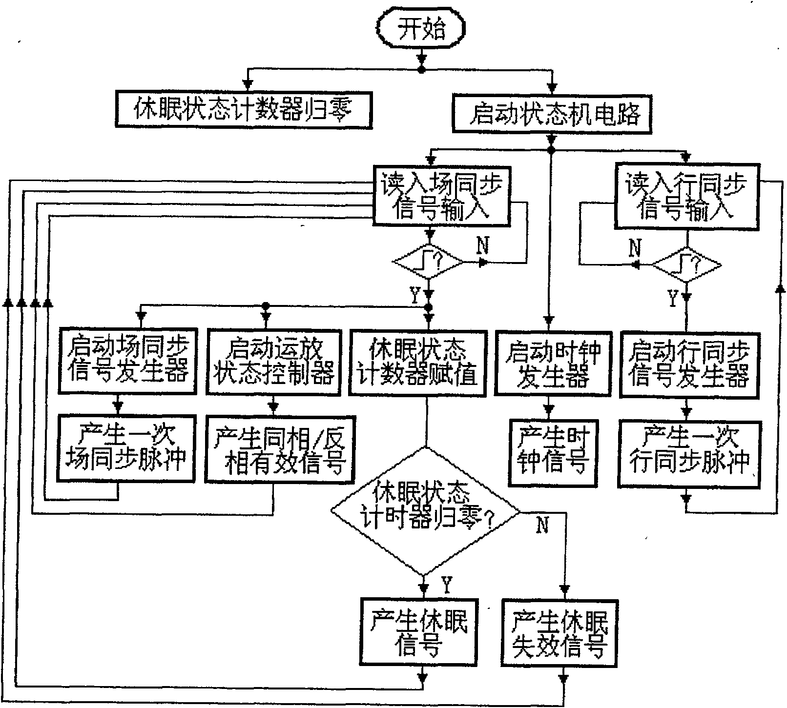
The invention relates to a drive circuit of an analogue type colorful near-eye liquid crystal display and the control method. The circuit has a RGB analog signal processing circuit module, a digital signal processing circuit module connected with the RGB analog signal processing circuit module, a multi-potential output voltage source circuit module that is respectively connected with the RGB analog signal processing circuit module and the digital signal processing circuit module. The digital signal processing circuit module has CPLD and crystal oscillator. The RGB analog signal processing circuit module has: a VGA interface connector and three analog video processing circuits with the same structure and connected with the VGA interface connector. The controlling method is that: the CPLD iselectrified, the dormant state counter is initialized and emits a dormancy signal; a state machine circuit is started to generate a clock signal, a read-in field synchronizing signal and a line synchronizing signal and judge the read-in signal; a one-time field synchronizing impulse and an in-phase / antiphase output signal are generated; judge the read-in line synchronizing signal; a line synchronizing pulse is generated. The circuit reduces the production cost, decreases the weight and the space volume of the control and driving circuit, reduces the power consumption of the whole machine andenhances the universality.

Description

technical field [0001] The invention relates to a near-eye liquid crystal display, in particular to an analog type that can achieve high system integration and meet the integrity and stability requirements of the display, and avoids the use of image decoding chips and reduces the power consumption of the whole machine. A driving circuit of a color near-eye liquid crystal display and a control method thereof. Background technique [0002] The rapidly rising portable mobile communication and wireless display products in recent years have an increasing demand for color near-eye display systems. The inherent advantages of color near-eye display systems determine the development prospects of mobile display products. Among them, the driving circuit of the color near-eye display and its control display method are the key points. The display driving circuit of the existing analog color near-eye liquid crystal display adopts IC chips with various types of functions in order to realiz...

Claims


Application Information

Patent Timeline
Patent Type & Authority Patents(China)
IPC IPC(8): G09G3/36
Inventor 范伟代永平范义
Owner SHENZHEN YANGTZE LIVETECH
Learn More