Eureka AIR delivers breakthrough ideas for toughest innovation challenges, trusted by R&D personnel around the world.

Microfluidic detection system and microfluidic detection method for real-time flow velocity of fluid

A detection system and microfluidic technology, applied in the direction of fluid velocity measurement, chemical instruments and methods, laboratory containers, etc., can solve the problems of high cost, added price, and increase the difficulty and cost of microfluidic chip production

Inactive Publication Date: 2020-03-31
浙江麦大基因科技有限公司
View PDF9 Cites 3 Cited by
  • Summary
  • Abstract
  • Description
  • Claims
  • Application Information

AI Technical Summary

Problems solved by technology

If a high-precision velocity sensor is placed in the microchannel, the fluid velocity near the sensor can be directly measured. This method increases the difficulty and cost of making the microfluidic chip, and the presence of the sensor will affect the flow velocity distribution in the microchannel. have a certain impact; and by recording the relative displacement of particles such as microbeads in the fluid over time, based on which the velocity of the fluid is deduced, such methods not only need to add expensive microbeads to the fluid, but also require spatial resolution Very tall microbead motion image capture device

Method used

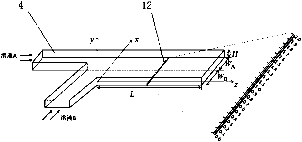
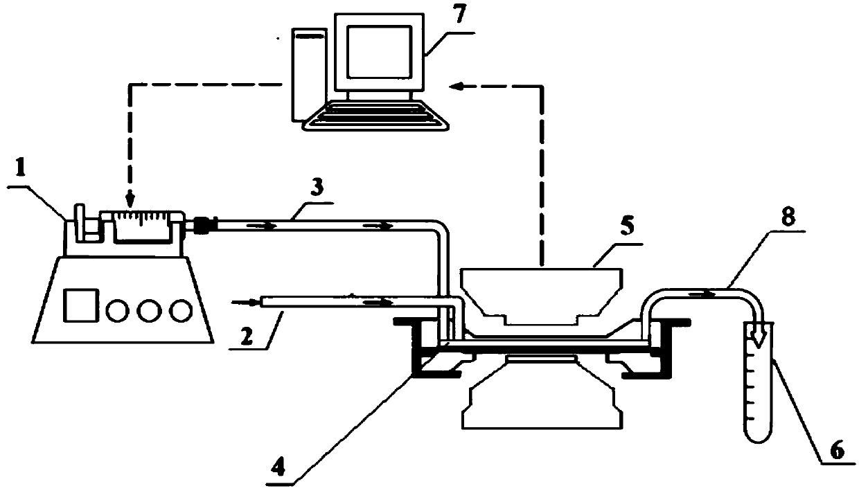
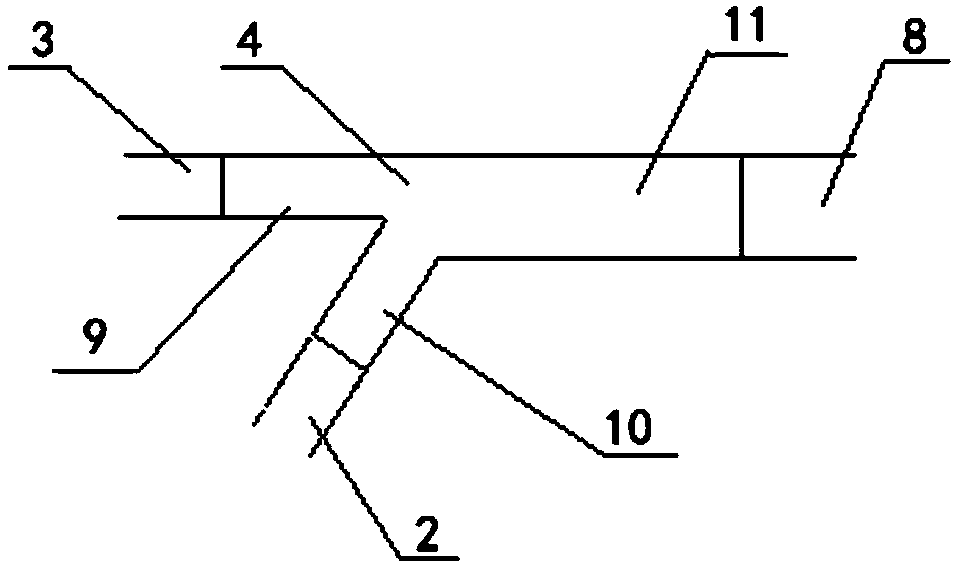

Image

  • Microfluidic detection system and microfluidic detection method for real-time flow velocity of fluid
  • Microfluidic detection system and microfluidic detection method for real-time flow velocity of fluid
  • Microfluidic detection system and microfluidic detection method for real-time flow velocity of fluid

Examples


Embodiment 1

[0042] Microfluidic detection system for real-time flow rate of fluid ( figure 2 ), including the programmable control pump 1 connected with a syringe, the fluorescence microscope 5 and the computer 7, and a uniform and flat dual-inlet microfluidic chip 4 ( figure 1 , image 3 ), the uniform and flat dual-entry microfluidic chip 4 is composed of the first liquid inlet pipe 9, the second liquid inlet pipe 10 and the confluence channel 11 and is a Y-shaped pipe. The cross section of the pipe is rectangular, and the first liquid inlet pipe 9 The included angle with the confluence channel 11 is 180°, and the included angle between the first liquid inlet pipe 9 and the second liquid inlet pipe 10 is 60° (any angle from 60° to 90° can also be used, such as 65°, 70° , 75°, 80°, 85°, 90°), the confluence channel is provided with a scale 12; the first liquid inlet tube 9 of the uniform and flat dual-entry microfluidic chip 4 is connected to the syringe through the first pipe 3, The seco...


PUM


Abstract

The invention discloses a microfluidic detection system and a microfluidic detection method for real-time flow velocity of a fluid. The system comprises a programmable control pump 1 connected with aninjector, a fluorescence microscope 5 and a computer 7, and further comprises a uniform and flat double-inlet micro-fluidic chip 4, wherein the uniform and flat double-inlet micro-fluidic chip 4 comprises a first liquid inlet pipe 9, a second liquid inlet pipe 10 and a convergence channel 11 and is a Y-shaped pipeline, the cross section of the pipeline is rectangular, scales 12 are arranged on the convergence channel, the uniform and flat double-inlet micro-fluidic chip 4 is movably arranged on the objective table of the fluorescence microscope 5, and the computer 7 is respectively and electrically connected with the programmable control pump 1 and the fluorescence microscope 5. According to the microfluidic detection system and the microfluidic detection method of the invention, the flowvelocity of a to-be-detected fluid can be rapidly detected, ie., the real-time flow velocity of the to-be-detected fluid, so that the basis is provided for quantitatively researching the movement rule of particles or fluids in a micro-channel and the cell mechanics behaviors.

Description

Technical field [0001] The invention belongs to the field of microfluidic technology experimental devices, and relates to a microfluidic detection system and a detection method of fluid real-time flow rate. Background technique [0002] Microfluidics (microfluidics) technology is increasingly being used in various fields due to its refined and quantitative advantages. In addition to observing the movement of particles or fluids under micro-scale conditions, it can also be used for cultivation in The cells in the microfluidic bottom channel are stimulated by shear force and are widely used to study cell biomechanics. How to measure the flow velocity of the fluid in the microfluidic chip is the key to quantitatively study the movement law of particles or fluid in the microchannel and the mechanical behavior of cells. [0003] At present, there are some common experimental methods in this field to determine fluid flow rate in microfluidic channels. If a high-precision velocity senso...

Claims


Application Information

Patent Timeline
Patent Type & Authority Applications(China)
IPC IPC(8): B01L3/00G01P5/26
CPCB01L3/5027G01P5/26
Inventor 李美航李扬兮刘爱国
Owner 浙江麦大基因科技有限公司
Why Eureka
Eureka Blog
Learn More