

Filtering method and device
A filter and filter intensity technology, applied in the field of video codec, can solve problems that affect the prediction accuracy of coded pixels, visual obstacles or artifacts, etc.
- Summary
- Abstract
- Description
- Claims
- Application Information
AI Technical Summary
Problems solved by technology
Method used
Image

Examples
Embodiment 1
[0124] Embodiment 1 is described by taking the application to the encoding end as an example.
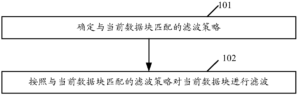
[0125] see figure 1 , figure 1 It is a flow chart of the filtering method provided in Embodiment 1 of the present application. This method is applied to the encoding end and may include the following steps:
[0126] Step 101, determine a filtering strategy matching the current data block.
[0127] Applied to the encoding end, the current data block here is one of the data blocks obtained by dividing the distortion video data (Distortion Data) at the encoding end. The distorted video data here refers to data that is distorted, such as pixel offset, compared to the original unencoded compressed video data, which can be reconstructed video data, or video data that has been filtered by the encoder using other filtering techniques for the reconstructed video data wait.
[0128] In an example, the encoding end may divide the distorted video data into data blocks of the same size or d...
Embodiment 2
[0280] see Figure 8 , Figure 8 It is a flow chart of the filtering method provided by Embodiment 2 of the present application. This method is applied to the encoding end and may include the following steps:
[0281] Step 801, determine a target filter for filtering the current data block.
[0282] In this step 801, there are many ways to realize the determination of the target filter used to filter the current data block, see the above-mentioned embodiment 1 figure 2 , Figure 4 The combination of the shown processes realizes an implementation manner of determining the target filter used for filtering the current data block in step 801, which will not be repeated here.
[0283] Step 802, when the target filter includes CNNF, select a candidate filter path matching the current data block from all candidate filter paths supported by CNNF as the target filter path, the candidate filter path supported by CNNF is composed of convolution kernels on at least one convolution l...
Embodiment 3
[0290] see Figure 9 , Figure 9 It is a flow chart of the filtering method provided in Embodiment 3 of the present application. This method is applied to the encoding end and may include the following steps:
[0291] Step 901, determine a target filter for filtering the current data block.
[0292] This step 901 is similar to the above step 801 and will not be repeated here.
[0293] Step 902, when the target filter includes CNNF, adjust the filter strength coefficient of the specified convolution layer in the CNNF to obtain the target filter strength coefficient.
[0294] There are many ways to implement this step 902 . The adjustment of the filter intensity coefficient of the specified convolutional layer in the CNNF described in the above-mentioned embodiment 1 to obtain the target filter intensity coefficient is one of the implementation ways, which will not be repeated here.
[0295] Step 903: Adjust the filtering strength of the CNNF for filtering the current data b...
PUM
 Abstract
Description
Claims
Application Information