Ring burning device and ring burning equipment

A technology of ring burner and inoculation ring, which is applied in sanitary equipment, water supply device, heating and other directions for toilets, can solve the problems of inoculation ring pollution, complicated operation, shortening the service life of inoculation ring, etc. Bacterial effect

Pending Publication Date: 2020-04-10
贵州金域医学检验中心有限公司
View PDF0 Cites 2 Cited by
  • Summary
  • Abstract
  • Description
  • Claims
  • Application Information

AI Technical Summary

Problems solved by technology

[0002] Sterilization is one of the important links in the process of tissue culture and bacterial culture. Currently, a ring burner is generally used to sterilize the inoculation loop. Put the loop in the burner and heat it to above 800°C, and the sterilization time is 5-10 seconds. After the sterilization is completed, move the inoculation loop to another place for cooling. There are the following problems during operation: First, the sterilization time The length of the inoculation loop is difficult to standardize and control. If the heating time is too short, the sterilization effect will not be good. If the heating time is too long, it will easily cause damage to the inoculation loop and reduce the service life of the inoculation loop; bracket, and remove the unsterilized inoculation loop from one bracket for disinfection and sterilization, and then place it on another bracket. The operation is complicated and inefficient, and it is easy to mistakenly put the sterilized inoculation loop back and place it unsterilized On the support of the inoculation loop, it will pollute the sterile inoculation loop

Method used


Image

  • Ring burning device and ring burning equipment
  • Ring burning device and ring burning equipment
  • Ring burning device and ring burning equipment

Examples


Embodiment Construction

[0035] In order to make the objectives, technical solutions and advantages of the present invention clearer, the present invention will be further described in detail below in conjunction with the accompanying drawings.

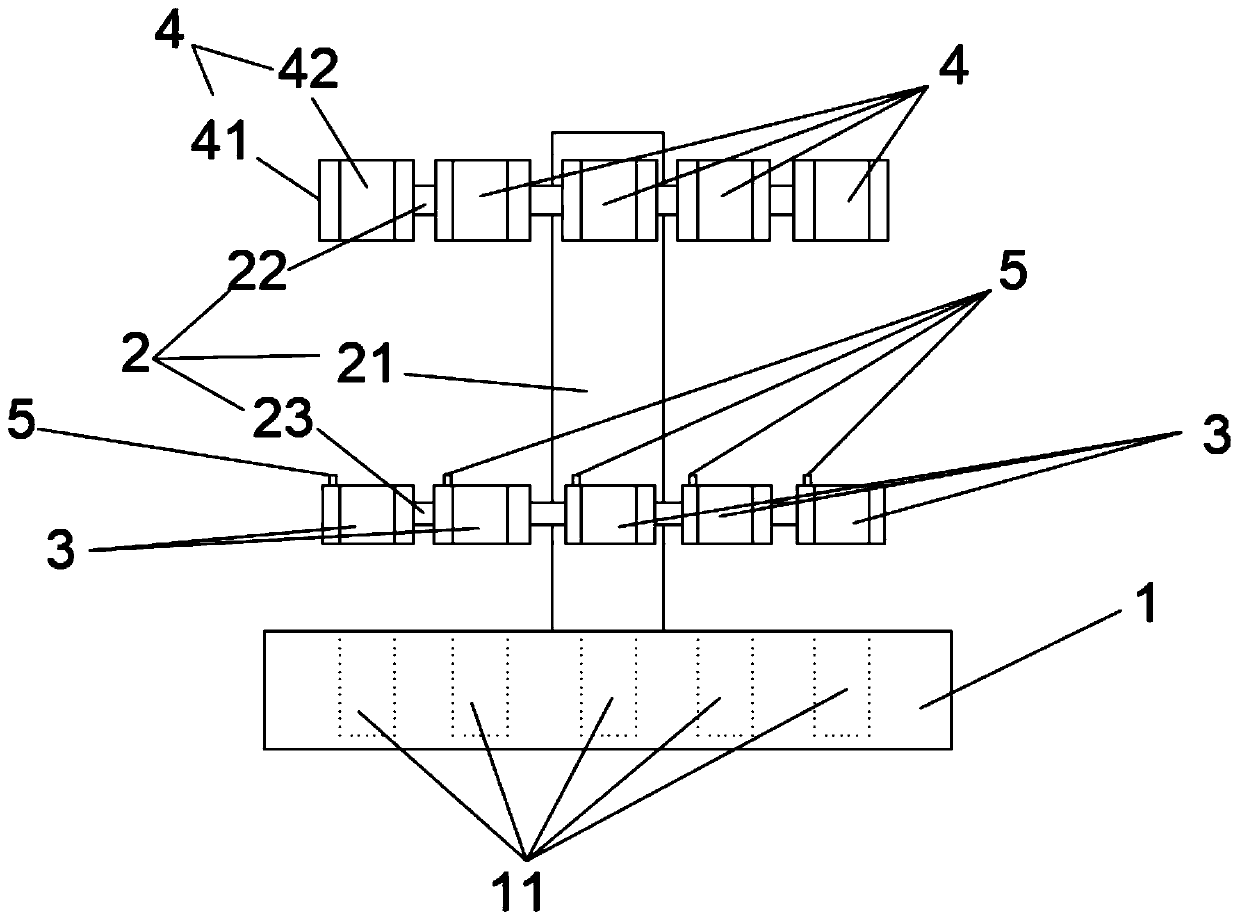
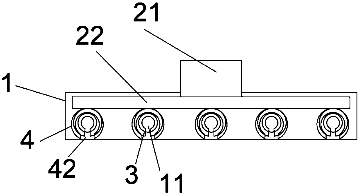
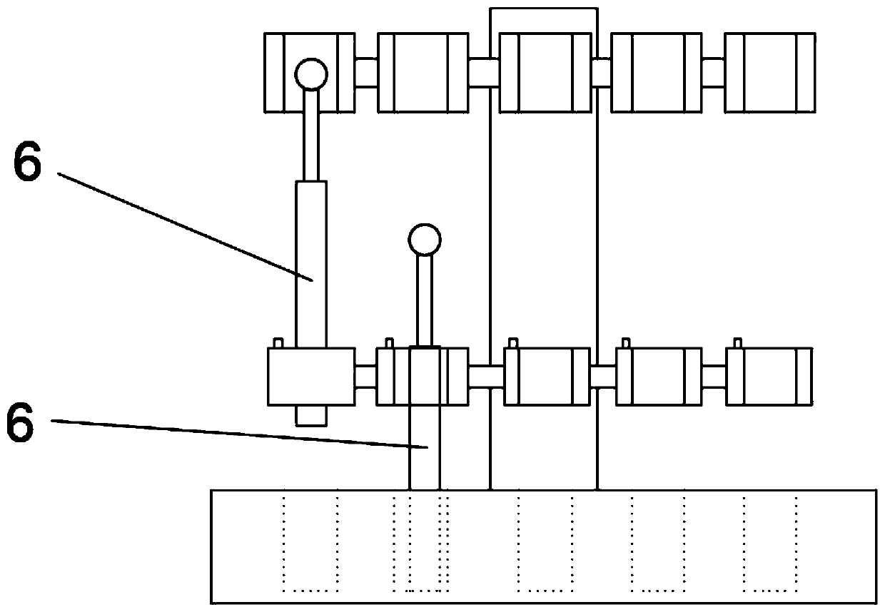
[0036] Such as Figure 1-Figure 5 As shown, the embodiment of the ring burning device disclosed in the present invention includes a support frame 2, a cooling seat 1, a clamp assembly 3, a heating element 4, an induction element 5, a timer and a controller, a cooling seat 1, a clamp assembly 3 and a heating The elements 4 are sequentially fixed on the support frame 2 in the same vertical direction from bottom to top. The sensing elements 5 are arranged on the support frame 2 and / or the clamp assembly 3. The cooling base 1 has a placement cavity 11 with an open top. 11 is directly below the fixture assembly 3, the distance from the bottom of the placement cavity 11 on the cooling seat 1 to the upper end of the fixture assembly 3 is less than the length of the ino...


PUM


Abstract

The invention discloses a ring burning device. The ring burning device comprises a supporting frame, a cooling base, a clamp assembly, a heating element, a sensing element, a timer and a controller. The cooling base, the clamp assembly and the heating element are sequentially fixed to the supporting frame in the same vertical direction from bottom to top. The sensing element is arranged on the supporting frame and/or the clamp assembly. The cooling base is provided with a containing cavity with an opening in the top, the containing cavity is located under the clamp assembly, the sensing element, the clamp assembly, and the heating element and the timer are all in data communication with the controller. The invention further discloses ring burning equipment comprising the ring burning device. According to the ring burning device and the ring burning equipment, the sterilization time of an inoculating loop can be controlled, automatic cooling is achieved after sterilization, transferringis not needed, and careless mistakes are not likely to happen.

Description

Technical field [0001] The invention relates to the field of biochemical experimental equipment, and in particular to a ring burning device and a ring burning device. Background technique [0002] Sterilization is one of the important links in the process of tissue culture and bacterial culture. Now the loop burner is generally used to sterilize the inoculation loop. When the loop burner disinfects and sterilizes the inoculation loop, you must hold the inoculation loop and inoculate The ring is placed in the ring burner and heated to above 800°C, and the sterilization time is 5-10 seconds. After the sterilization is completed, the inoculation ring is moved to another place for cooling. The following problems exist during operation: First, the sterilization time The length of the inoculation loop is difficult to standardize control. If the heating time is too short, the sterilization effect is not good. If the heating time is too long, it is easy to damage the inoculation loop and...

Claims


Application Information

Patent Timeline
Patent Type & Authority Applications(China)
IPC IPC(8): A61L2/04A61L2/26A61L2/24
CPCA61L2/04A61L2/24A61L2/26A61L2202/14
Inventor 龙宇杨坚付正乾黄松刘婷彭潮燕
Owner 贵州金域医学检验中心有限公司
Why Eureka
Try Eureka