Y-shaped flow regulating and pressure regulating valve

A pressure regulating valve and flow regulating technology, which is applied in the direction of sliding valves, valve details, valve devices, etc., can solve the problems of starting failure, short linear adjustment stroke, and low adjustment accuracy, so as to improve the service life, increase the flow regulation range, Good effect of adjustable performance

Pending Publication Date: 2020-04-10
TIANJIN TANGGU WATTS VALVE CO LTD
View PDF0 Cites 2 Cited by
  • Summary
  • Abstract
  • Description
  • Claims
  • Application Information

AI Technical Summary

Problems solved by technology

[0003] In the existing Y-type flow regulating and pressure regulating valve, the flow holes provided on the top are generally evenly distributed on the flow regulating sleeve, and the regulating precision is low when the valve is throttled. When the valve is in the middle opening, the linear regulating stroke is short and easy to adjust. Dirt jamming
[0004] In addition, there is no sealing ring between the lower part of the sliding sleeve and the valve seat. When the valve is opened or closed, during the adjustment stroke of the sliding sleeve, due to hydraulic impact, the sliding sleeve is prone to vibration, resulting in a gap between the lower part of the sliding sleeve and the valve seat. The problem of not tight fit, which will cause leakage;
[0005] Furthermore, for some valves with larger specifications, the height of the bonnet is relatively high, and the adjustment stroke of the internal flow adjustment sleeve is long. During the adjustment process, it is necessary to prevent the valve stem from driving the sliding sleeve to rotate. Executing a fixed opening stroke, resulting in failure at the beginning or failure to achieve the expected opening or closing stroke, unable to meet the expected flow and pressure regulation effect

Method used


Image

  • Y-shaped flow regulating and pressure regulating valve
  • Y-shaped flow regulating and pressure regulating valve
  • Y-shaped flow regulating and pressure regulating valve

Examples


Embodiment Construction

[0024] In order to make the object, technical solution and advantages of the present invention more clear, the present invention will be further described in detail below in conjunction with the examples. It should be understood that the specific embodiments described here are only used to explain the present invention, not to limit the present invention.

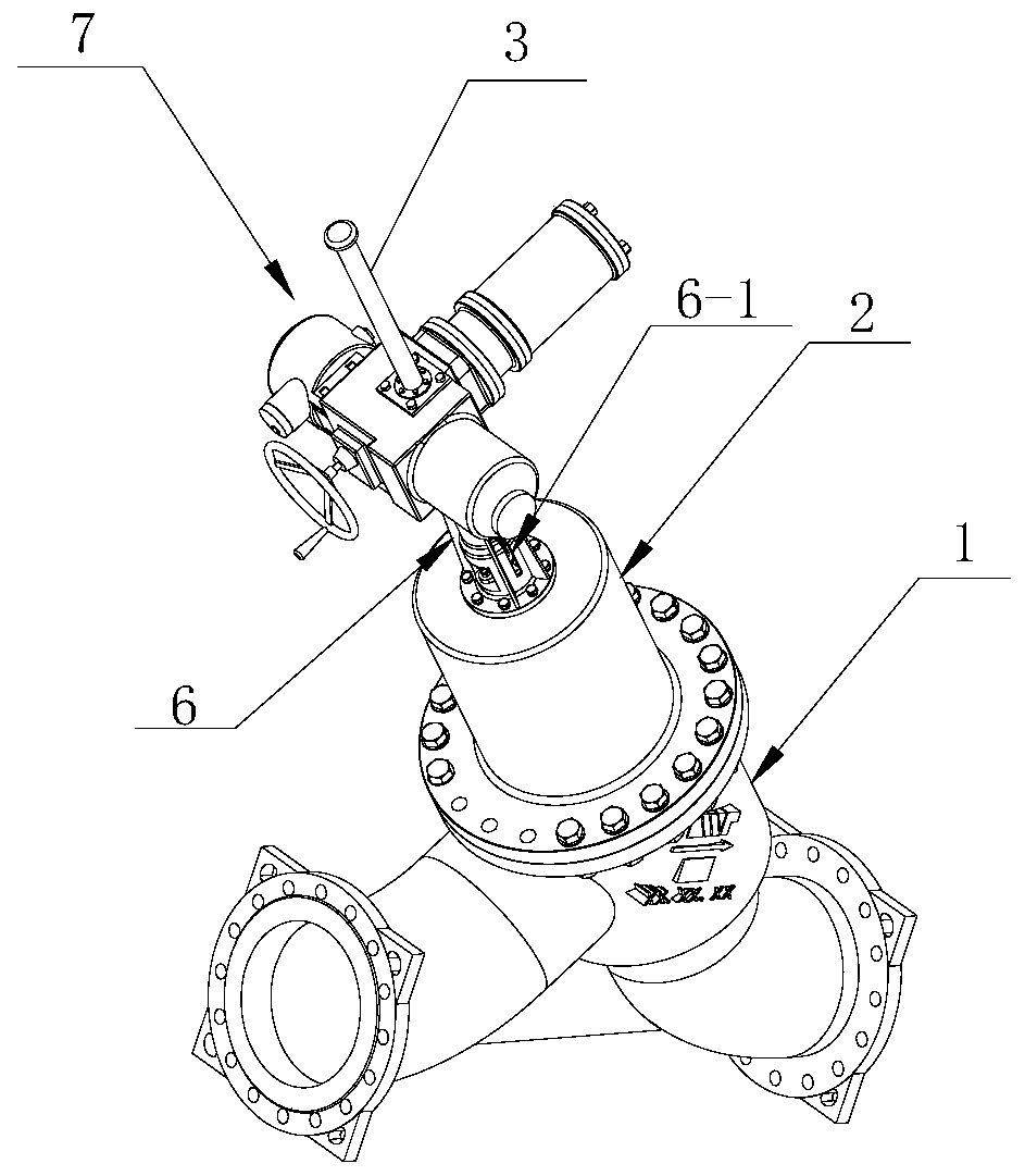
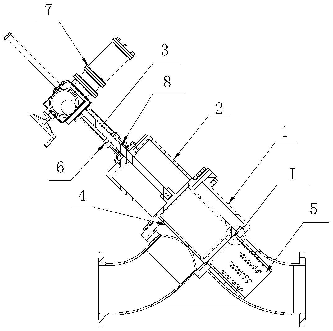
[0025] Please refer to the figure, the present invention is achieved in this way, a Y-type flow regulating and pressure regulating valve includes a valve body 1, a valve cover 2 installed on the valve body, a valve stem 3 installed on the valve cover, and A sliding sleeve 4 is installed on the valve stem, the lower end of the sliding sleeve is connected with a flow regulating sleeve 5, the upper end of the valve stem extends out of the valve cover, and a valve stem bracket 6 is installed on the upper end of the valve cover. , the valve stem is worn in the valve stem bracket, and the drive device 7 for driving the valve stem...


PUM


Abstract

The invention discloses a Y-shaped flow regulating and pressure regulating valve. The Y-shaped flow regulating and pressure regulating valve comprises a valve body, a valve cover, a valve rod, a sliding sleeve, a flow regulation sleeve, a valve rod bracket and a driving device, wherein the flow regulation cylinder comprises a cylinder body, arrays of overflowing holes are formed in the side wall of the cylinder body; every two arrays of the overflowing holes form a group; the centers of the overflowing holes in every two arrays are staggered; the overflowing holes in the same array are at least divided into an overflowing region and a blow down rinsing region from top to bottom; a plurality of main regulating overflowing holes of which the hole diameters are the same are arranged on each overflowing region; a plurality of blow down rinsing overflowing holes are formed in each blow down rinsing region; the hole diameter of the blow down rinsing overflowing holes is greater than that ofthe main regulating overflowing holes in each main regulating overflowing region; a throttling region is also arranged in one side adjacent to the sliding sleeve, at the upper parts of the overflowingregions of two symmetric groups of the overflowing holes; a plurality of throttling overflowing holes are formed in the throttling region; the hole diameter of the throttling overflowing holes is smaller than that of the overflowing holes in each overflowing region; and two arrays of the throttling overflowing holes in the same group are staggered. The Y-shaped flow regulating and pressure regulating valve disclosed by the invention has the advantages of being large in flow regulating and pressure regulating range, high in flow regulating precision, small in valve vibration, low in noise andthe like.

Description

technical field [0001] The invention belongs to the technical field of valves, and in particular relates to a Y-shaped flow regulating and pressure regulating valve suitable for a pressure regulating working condition with a large pressure difference between the front of the valve and the back of the valve. Background technique [0002] Y-type flow regulating and pressure regulating valve is suitable for the precise adjustment of flow and pressure in the pipeline system. When the valve is working, the driving device on its upper part drives the valve stem to move up and down (upward to open the valve, and downward to close the valve), the valve stem drives the sliding sleeve, and the sliding sleeve drives the flow regulating sleeve fixed on it to move, through the flow regulating sleeve The change of the cross-section of the flow hole designed above completes the pressure and flow adjustment of the set parameters of the pipeline. [0003] In the existing Y-type flow regulat...

Claims


Application Information

Patent Timeline
IPC IPC(8): F16K3/24F16K3/314F16K47/08
CPCF16K3/24F16K3/314F16K47/08
Inventor 王展波王洋
Owner TIANJIN TANGGU WATTS VALVE CO LTD
Why Eureka
Try Eureka