Overpressure valve for hydraulic device

A technology of hydraulic devices and overpressure valves, which is applied in the field of overpressure valves, can solve problems such as inconvenient maintenance of parts, poor sealing effect of overpressure valves, and inability to meet the needs of use, so as to facilitate maintenance, ensure sealing effects, and overcome sealing problems. less effective effect

Inactive Publication Date: 2020-04-10
湖南天泓液压机械有限公司
View PDF12 Cites 2 Cited by
  • Summary
  • Abstract
  • Description
  • Claims
  • Application Information

AI Technical Summary

Problems solved by technology

[0004] The purpose of the present invention is to provide an overpressure valve for a hydraulic device to solve the problem that the valve body of the overpressure valve proposed in the above-mentioned background technology is mostly integrally formed, so that the molding is difficult and the production cost is high during the production process. The production cycle is long, and at the same time, because it cannot be disassembled, it brings inconvenience to the maintenance of its internal parts, and the sealing effect of the traditional overpressure valve is poor, which reduces its service life and poor practicability, which can no longer meet the existing market The problem of usage requirements

Method used


Image

  • Overpressure valve for hydraulic device
  • Overpressure valve for hydraulic device
  • Overpressure valve for hydraulic device

Examples


Embodiment Construction

[0026] The following will clearly and completely describe the technical solutions in the embodiments of the present invention with reference to the accompanying drawings in the embodiments of the present invention. Obviously, the described embodiments are only some, not all, embodiments of the present invention. Based on the embodiments of the present invention, all other embodiments obtained by persons of ordinary skill in the art without making creative efforts belong to the protection scope of the present invention.

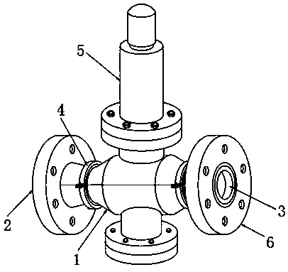
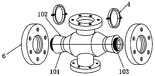
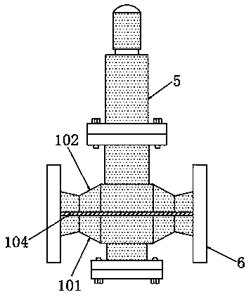
[0027] see Figure 1-6 , in an embodiment of the present invention, an overpressure valve for a hydraulic device includes a valve body 1, one end of the valve body 1 is provided with an input port 2, and the other end is provided with an output port 3, and the outer side of the valve body 1 is sleeved with a The fixed assembly 4, the valve cover 5 is fixedly installed on the upper end of the valve body 1, and the two ends of the valve body 1 are provided with ...


PUM


Abstract

The invention discloses an overpressure valve for a hydraulic device and relates to the technical field of hydraulic devices. The overpressure valve comprises a valve body. An input port is formed inone end of the valve body while an output port is formed in the other end of the valve body. A fixing assembly is arranged on the outer side of the valve body in a sleeving manner. A valve cover is fixedly mounted at the upper end of the valve body, flanges are arranged at two ends of the valve body in a sleeving manner, a valve seat A is arranged at the bottom of the valve body, a spring seat A is mounted in the valve seat A, and a spring A is mounted at the upper end of the spring seat A. By arranging the valve body in a split structure, a defect that it is inconvenient to manufacture and form the valve body of a conventional overpressure valve as the valve body of the conventional overpressure valve is integrally formed is overcome, so that convenience is brought to production and manufacturing of the overpressure valve, and the overpressure valve is of relatively high practicality. By means of a rubber liner A, a seal ring A and a seal ring B which are arranged, the overpressure valve has multiple sealing structures, and overcomes the defect that the conventional overpressure valve is relatively poor in sealing effect, so that the sealing property of the overpressure valve is improved effectively, the service life of the overpressure valve is prolonged and the overpressure valve is suitable for being widely popularized.

Description

technical field [0001] The invention relates to the technical field of hydraulic devices, in particular to an overpressure valve for hydraulic devices. Background technique [0002] A pressure control valve is a valve used to control and regulate the pressure of liquid flow in a hydraulic system. This type of valve works on the principle that the liquid pressure acting on the spool is balanced with the spring force. Pressure control valves include pressure reducing valves, overflow valves, sequence valves, and balance valves. The pressure reducing valves are adjusted to The valve that reduces the inlet pressure to a certain required outlet pressure and relies on the energy of the medium itself to automatically maintain the outlet pressure is also called an overpressure valve. [0003] However, most of the overpressure valves for hydraulic devices currently on the market have integrally formed valve bodies, which makes it difficult to form during the production process, with...

Claims


Application Information

Patent Timeline
Patent Type & Authority Applications(China)
IPC IPC(8): F16K17/04F16K27/02
CPCF16K17/044F16K27/02
Inventor 谭梁昊张静云
Owner 湖南天泓液压机械有限公司
Why Eureka
Try Eureka