
Suspended ceiling structure

A technology for suspended ceilings and keels, which is applied in the direction of ceilings, building components, and building structures, and can solve problems such as reduced clamping force of connecting clamps, potential safety hazards, and aging of triangular keels, so as to avoid loose clamping and use Long life, labor-saving plugging effect

Pending Publication Date: 2020-04-14
FSILON BUILDING MATERIAL TECH CO LTD
View PDF0 Cites 0 Cited by
  • Summary
  • Abstract
  • Description
  • Claims
  • Application Information

AI Technical Summary

Problems solved by technology

[0002] Suspended ceiling refers to the top decoration of the indoor ceiling of a house. The use of suspended ceilings in the prior art is quite extensive. At present, in the suspended ceiling installed on the top of the room, the panels are generally fixed by triangular keels, and the panels are inserted into the triangular keels through connecting clamps. In the gap, press the bayonet of the connecting clamp through the gap to achieve fixation. When the ceiling installation time is too long or it is installed in an environment with poor conditions such as kitchen and bathroom, the triangular keel is likely to be aging. The clamping force on the connecting clamp will become smaller to a certain extent. Under the action of its own gravity, the panel is likely to drive the connecting clamp to fall, posing a safety hazard; It is clamped in the form of wire contact, and it is relatively difficult to clamp in

Method used


Image

  • Suspended ceiling structure
  • Suspended ceiling structure
  • Suspended ceiling structure

Examples


Embodiment Construction

[0032] The following are specific embodiments of the present invention and in conjunction with the accompanying drawings, the technical solutions of the present invention are further described, but the present invention is not limited to these embodiments.

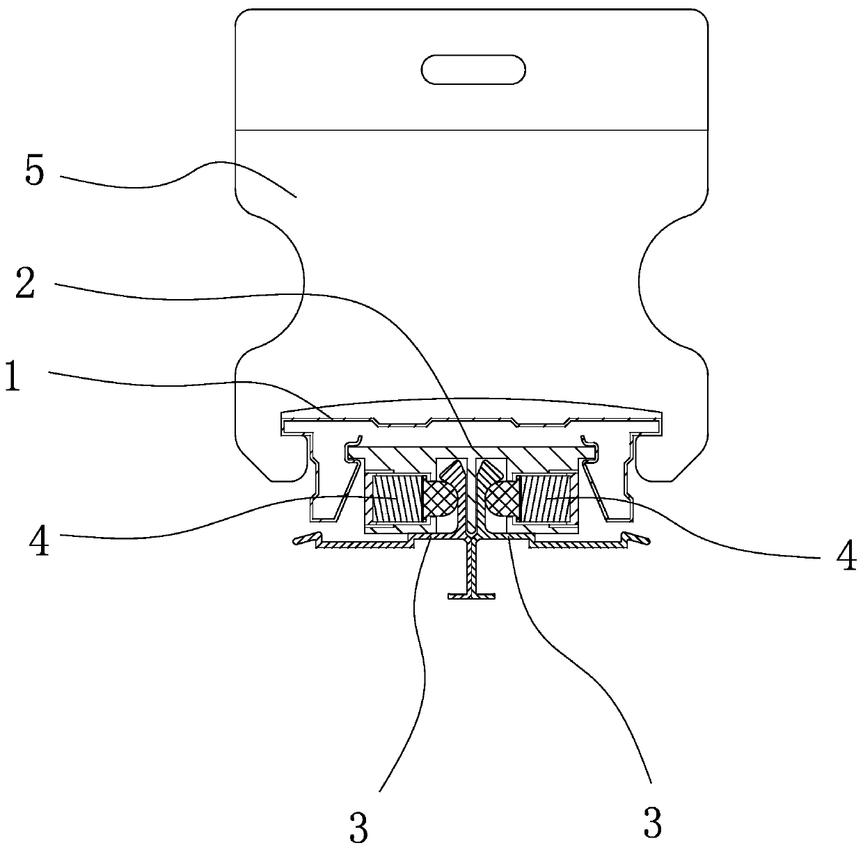
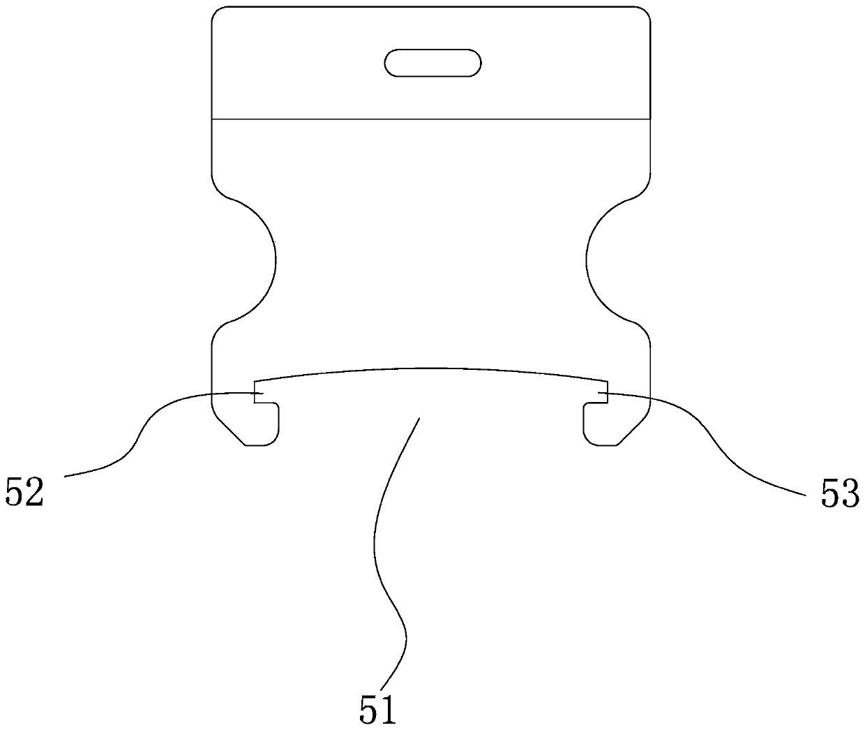
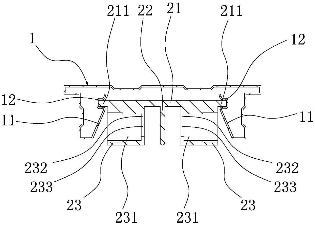
[0033] refer to Figure 1-Figure 5 , the present embodiment is a suspended ceiling structure, including a hook 5, a keel piece 1, a keel piece 2 and a connecting clamp 3, the hook 5 is fixed on the top of the wall, the keel piece 1, the keel piece 2 and The connecting clips 3 are all long strip profiles, the keel part 1 is clipped with the hook 5, the keel part 2 is clipped with the keel part 1, and the connecting clip 3 is connected to the keel part 2 through several groups of spring positioning components 4. The two phases are clamped, and each spring positioning assembly 4 is sequentially arranged at intervals along the length direction of the second keel member 2 . Specifically, a keel slot 51 is provided below the ho...


PUM


Abstract

The invention provides a suspended ceiling structure, belongs to the technical field of decorative building materials, and solves the problem that an existing suspended ceiling is inconvenient to mount and easy to age and fall off. The suspended ceiling structure comprises a keel part I, a keel part II and a connecting clamping plate. The keel part I and the keel part II are in clamping connection, the connecting clamping plate is connected to the keel part II through a plurality of spring positioning assemblies in a clamping manner, and the spring positioning assemblies are successively arranged in a spaced manner along the length direction of the keel part II. As the connecting clamping plate and the keel part II are in clamping connection through the spring positioning assemblies, a conventional line contact clamping mode is changed to a point contact clamping mode, so that it is more labor-saving to insert and meanwhile, the suspended ceiling structure is unlikely to age and fall off.

Description

technical field [0001] The invention belongs to the technical field of decoration and building materials, and relates to a suspended ceiling structure. Background technique [0002] Suspended ceiling refers to the top decoration of the indoor ceiling of a house. The use of suspended ceilings in the prior art is quite extensive. At present, in the suspended ceiling installed on the top of the room, the panels are generally fixed by triangular keels, and the panels are inserted into the triangular keels through connecting clamps. In the gap, press the bayonet of the connecting clamp through the gap to achieve fixation. When the ceiling installation time is too long or it is installed in an environment with poor conditions such as kitchen and bathroom, the triangular keel is likely to be aging. The clamping force on the connecting clamp will become smaller to a certain extent. Under the action of its own gravity, the panel is likely to drive the connecting clamp to fall, posing...

Claims


Application Information

Patent Timeline
IPC IPC(8): E04B9/06E04B9/18
CPCE04B9/065E04B9/18
Inventor 蔡凌雲沈正华殷正超
Owner FSILON BUILDING MATERIAL TECH CO LTD
Learn More