
Control box and electric lifting table

A control box and control circuit board technology, which is applied to tables, electrical components, printed circuit board sockets, etc., can solve the problems of low yield, inability to meet fast assembly, time-consuming and labor-intensive problems, etc.

Pending Publication Date: 2021-07-30
ZHEJIANG LEGE INTELLIGENT DRIVE TECH CO LTD
View PDF0 Cites 0 Cited by
  • Summary
  • Abstract
  • Description
  • Claims
  • Application Information

AI Technical Summary

Problems solved by technology

There are many control circuits integrated on the circuit board in the control box of the prior art. If a control circuit fails to be etched or has been used for a long time and has poor contact, the entire circuit board must be replaced, resulting in waste of resources and low yield; Furthermore, the installation of the circuit board is very cumbersome, time-consuming and laborious, and cannot meet the needs of rapid assembly

Method used


Image

  • Control box and electric lifting table
  • Control box and electric lifting table
  • Control box and electric lifting table

Examples


Embodiment 1

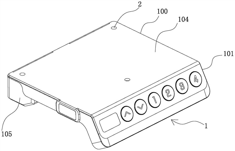
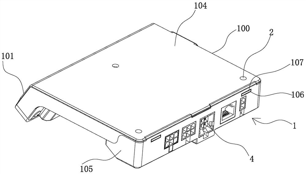
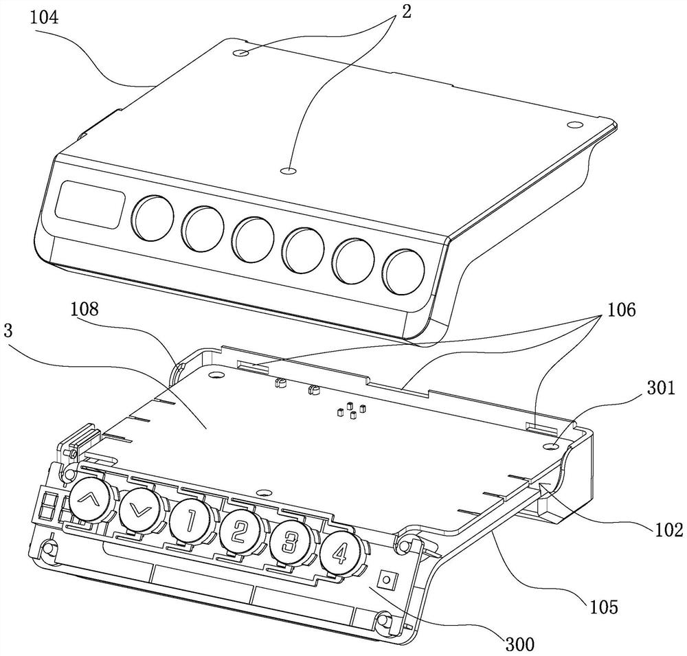
[0031] see Figure 1 to Figure 5 shown;

[0032] The present invention is a control box, which includes a box body 1, which has a straight side portion 100 connected to the bottom of the table and an inclined portion 101 that is inclined downward and forms a certain angle with the straight side portion 100. The inclined portion 101 It is arranged on the side of the box body 1 close to the user. The straight side part 100 of the box body 1 is provided with a first installation space 102, and the inclined part 101 is provided with a second installation space 103; The side part 100 is provided with a plurality of connection holes 2 extending along the thickness direction of the box body 1 and respectively penetrating through the top and bottom of the straight side part 100; the first control circuit board 3 is arranged in the first installation space 102, and the first control circuit board 3 The circuit board 3 is provided with a through hole 301 corresponding to the connection...

Embodiment 2

[0039] see Figure 6 ~ Figure 7 shown;

[0040] A control box of the present invention, it also includes two slots 113 on the two side walls of the first end of the upper case 104, and two slots 113 on the two side walls of the first end of the lower case 105. When the upper casing 104 and the lower casing 105 are closed, the two sockets 114 are plugged into the two slots 113. Two first clamping holes 115 are provided on the two side walls of the straight side portion 100 of the upper housing 104 , and two first clamping holes 115 are provided on the two side walls of the straight side portion 100 of the lower housing 105 . The first clamping block 116 that matches and engages; the edge of the inclined part 101 of the upper housing 104 is provided with at least one second clamping hole 117, and the edge of the inclined part 101 of the lower housing 105 is provided with the second clamping hole 117 The second clamping block 118 is matched with the clamping joint. When the up...


PUM


Abstract

The invention discloses a control box and an electric lifting table. The control box comprises a box body, a first control circuit board and a second control circuit board. The box body is provided with a straight edge part and an inclined part, a first mounting space is arranged in the straight edge part, and a second mounting space is arranged in the inclined part. A plurality of connecting holes which extend along the thickness direction of the box body and respectively penetrate through the top and the bottom of the straight edge part are formed in the straight edge part of the box body. The first control circuit board is arranged in the first mounting space and is provided with through holes communicated with the connecting holes in a one-to-one correspondence mode. When connecting screws connected with the bottom of a table board are arranged in the connecting holes of the straight edge part in a penetrating mode, the connecting screws penetrate through the through holes in the first control circuit board to limit the first control circuit board in the first mounting space. The second control circuit board is electrically connected with the first control circuit board. According to the control box and the electric lifting table, the circuit board of the control box is reasonable in layout, the structure is novel, installation is convenient, easy and stable, and the requirement of people for rapid assembly can be met.

Description

technical field [0001] The invention relates to the technical field of electric lifting tables, in particular to a control box and electric lifting tables. Background technique [0002] The electric adjustable desk is a height-adjustable desk, which can be adjusted according to a person's height, sitting posture and standing posture. The structure of the electric lift table generally includes a table board, a beam, a base and a lift table leg. The lift table leg includes a plurality of sleeves that are sequentially socketed from the inside to the outside. A linear lifting mechanism is provided in the innermost sleeve. The linear lifting mechanism It is a lead screw and nut pair, the rotation of the lead screw drives the nut to move along the length direction of the lead screw; a drive motor is provided on the beam, and the drive motor drives the transmission rod in the beam to rotate, and the two ends of the drive rod respectively connect with the linear lifting mechanism in...

Claims


Application Information

Patent Timeline
IPC IPC(8): H05K5/02H05K7/14A47B9/00
CPCA47B9/00H05K5/0217H05K7/1422
Inventor 项乐宏邵同旺汪颂力沈浩杰
Owner ZHEJIANG LEGE INTELLIGENT DRIVE TECH CO LTD
Learn More