
test connector

A technology of test connectors and connecting arms, which is applied in the direction of test/measurement connectors, connections, parts of connection devices, etc. It can solve the problems that modules cannot be dynamically tested, and test connectors cannot be reliably connected to modules under test. , to achieve the effect of labor-saving plugging and reliable connection

Active Publication Date: 2019-06-07
CHINA AVIATION OPTICAL-ELECTRICAL TECH CO LTD
View PDF4 Cites 0 Cited by
  • Summary
  • Abstract
  • Description
  • Claims
  • Application Information

AI Technical Summary

Problems solved by technology

[0004] The purpose of the present invention is to provide a test connector to solve the problem that the existing test connector cannot be firmly connected to the module to be tested, and the module obtained by mating cannot be dynamically tested.

Method used


Image

  • test connector
  • test connector
  • test connector

Examples


Embodiment Construction

[0022] Embodiments of the present invention will be further described below in conjunction with the accompanying drawings.

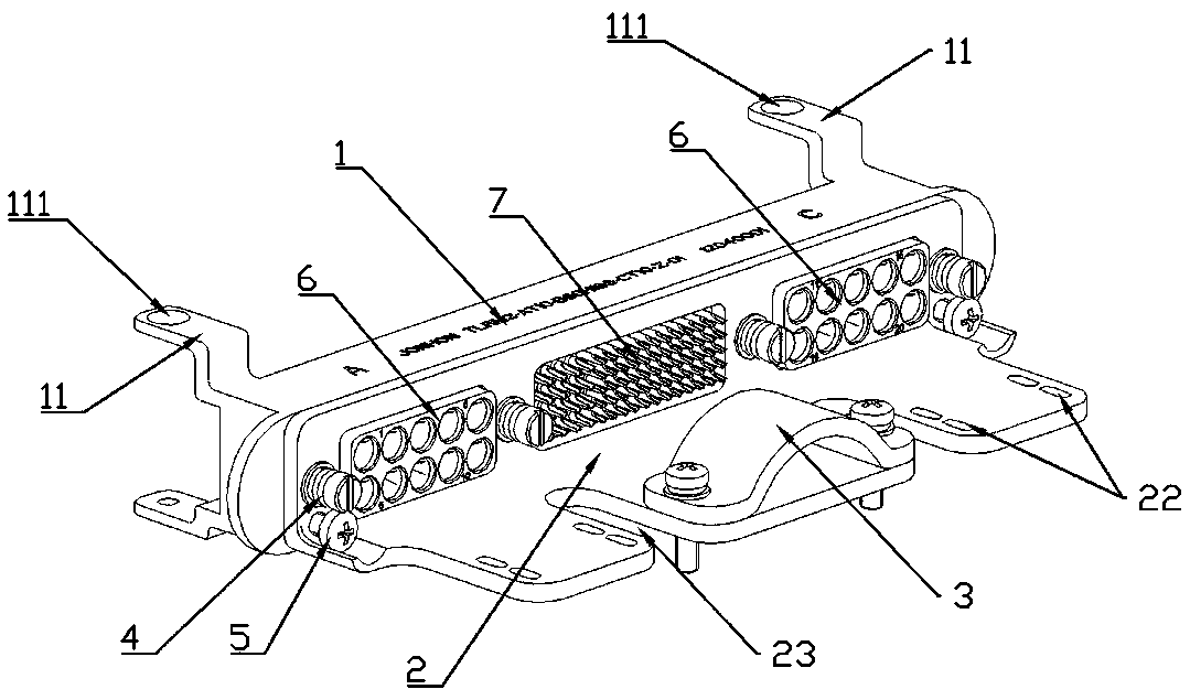
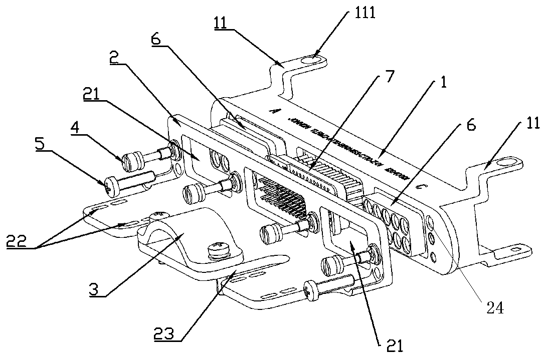
[0023] Specific embodiments of the test connector of the present invention, such as Figure 2 to Figure 4 As shown, the base 1 includes a cuboid block structure. The base 1 is provided with three square escape grooves at intervals in the length direction of the base 1 . The escape grooves penetrate the front and rear side walls of the base 1 . In this embodiment, the avoidance groove in the middle position is used for inserting the low-frequency socket part 7, and the two avoidance grooves near the left and right side walls of the base 1 are respectively used for inserting two high-frequency socket parts 6.

[0024] Two positions on the top wall of the base 1 near the left and right ends of the base 1 and two positions on the bottom wall of the base 1 near the left and right ends of the base 1 are respectively provided with connecting arms 11 that cantil...


PUM


Abstract

The invention relates to a test connector in the field of connectors. The test connector comprises a base. The base is equipped with a base connecting structure used for being fixedly connected with a to-be-tested module, and is further equipped with avoiding slots for module plug components on the to-be-tested module or test plug components matching the module plug components to pass through in such a way that the test plug components and the module plug components are in plug fit. The test connector further comprises a pressure plate used for pushing the test plug components to move towards the module plug components. A locking structure used for pressing the pressure plate to make the pressure plate move towards the test plug components is arranged between the pressure plate and the base. During use of the test connector, the base is fixed on the to-be-tested module, the test plug components are placed on the base, the locking structure drives the pressure plate to move, and the pressure plate presses against the test plug components to make the test plug components in plug fit with the module plug components. The base is connected firmly connected with the to-be-tested module. The to-be-tested module can be tested dynamically after being connected, and plugging is more labor-saving.

Description

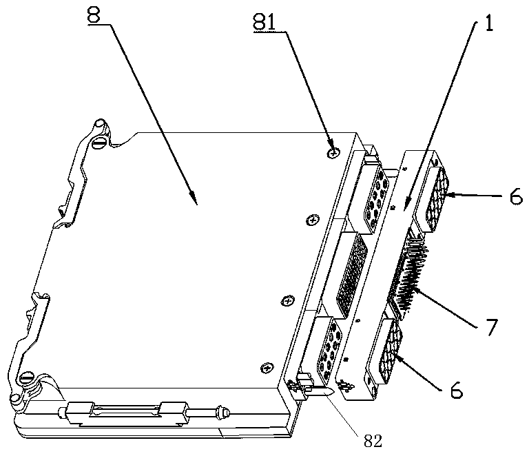
technical field [0001] The present invention relates to a connector for testing in the field of connectors. Background technique [0002] The test connector is mainly used to test the sub-board module. The existing connection method between the test connector and the sub-board module is as follows: figure 1 As shown, three plug parts are arranged on the side wall of the sub-board module 8, wherein the plug part in the middle is a low-frequency plug part, and the two plug parts arranged on both sides of the high-frequency plug part are high-frequency plug parts. The screws on the top and bottom surfaces of the sub-board module are fixed, and the top and bottom surfaces of the sub-board module 8 are respectively provided with four screw holes 81 for the above-mentioned screw installation. The test connector includes a base 1 with a cuboid block structure. The base 1 is provided with three socket parts that match the plug parts on the sub-board module 8. The socket parts inclu...

Claims


Application Information

Patent Timeline
Patent Type & Authority Patents(China)
IPC IPC(8): H01R13/50H01R13/639H01R13/631H01R13/533H01R27/02
CPCH01R13/50H01R13/533H01R13/631H01R13/639H01R27/02H01R2201/20
Inventor 张小虎潘娟娟
Owner CHINA AVIATION OPTICAL-ELECTRICAL TECH CO LTD
Learn More