A pipe clamping device and method of use

A technology of pipes and clasps, which is applied in the direction of pipe connection layout, pipes/pipe joints/fittings, mechanical equipment, etc. It can solve the problems of pipe pulling, affecting the sealing effect of joints, and water leakage, so as to save manpower and material resources and reduce water pipes. Excellent maintenance and operability

Active Publication Date: 2021-03-26
CHINA MCC20 GRP CORP
View PDF7 Cites 0 Cited by
  • Summary
  • Abstract
  • Description
  • Claims
  • Application Information

AI Technical Summary

Problems solved by technology

[0002] Pipelines are used in many industries, including industrial applications and daily life applications, and there are many types of pipe materials. For some large metal pipes, there are generally flanges connected to each other, and then bolts are used. Generally speaking, the connection is relatively stable, but for some thin plastic pipe fittings, joints are generally used for connection, and heating is used, such as between temporary water pipes on the construction site and domestic water pipes. If the connection is not firm, water leakage will occur after long-term use, which will affect the water situation at the construction site. When some steel wire skeleton plastic water supply pipes are used for water or other purposes, splicing is required because the length of the pipe is not enough. Generally, hot-melt connection is used to soften the interface, and then docking is performed. After docking, no further fixed connection is made.
However, there are often severe vibrations or pulling on the pipelines at the construction site, which may cause loosening or opening of the joints, causing water to flow out and waste water resources. Therefore, the connection between pipelines needs to be improved.
Existing connections between plastic pipes or metal pipes are generally connected through an integral hoop, but as the sealing layer in the hoop wears, it will also affect the sealing effect of the joint

Method used


Image

  • A pipe clamping device and method of use
  • A pipe clamping device and method of use
  • A pipe clamping device and method of use

Examples


Embodiment Construction

[0021] The present invention is further illustrated below by specific examples.

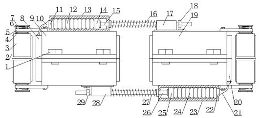
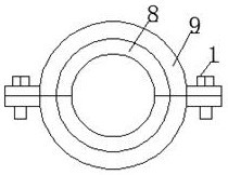
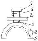
[0022] Such as Figure 1~Figure 3 As shown, a pipe clamping device includes a first snap ring 9 and a second snap ring 19, and fastening screws 1 are symmetrically installed between the first snap ring 9 and the second snap ring 19, and the first snap ring 9 and the second clasp 19 outer sides are all symmetrically fixedly equipped with a connecting plate 5, the connecting plate 5 is provided with a slide bar 4, the upper side of the slide bar 4 surface is provided with a first coil spring 6, and the outer end of the slide bar 4 is welded with a Baffle plate 7, push ring 3 is welded on the inner end of slide rod 4, anti-skid layer 2 is fixedly installed on the inner surface of push ring 3, first guide tube 13 is welded on the upper surface of first snap ring 9, and first guide tube 13 is sleeved inside There is a first telescopic airbag 12, the first airbag 11 is fixedly installed on the left en...


PUM


Abstract

The invention relates to the field of electromechanics and pipe installation, in particular to a pipe clamping device. The pipe clamping device comprises a first clamping ring (9) and a second clamping ring (19), fastening screws (1) are symmetrically installed between the first clamping ring (9) and the second clamping ring (19), and the first clamping ring (9) and the second clamping ring (19) form a whole circle; and a connecting plate (5) is connected with the first clamping ring (9) and the second clamping ring (19) through screws. A water pipe constructed through the method can be recycled, subsequent water pipe maintenance is greatly reduced, and therefore manpower and material resources are saved. Meanwhile, the method and the device are high in operability, the device is stably clamped at the connecting position of the pipe, leakage caused by looseness of the connecting position of the pipe is prevented, the design is reasonable, operation is convenient, and the target requirement of pipe clamping operation is met.

Description

technical field [0001] The invention relates to the field of electromechanical and pipeline installation, in particular to a pipeline clamping device. Background technique [0002] Pipelines are used in many industries, including industrial applications and daily life applications, and there are many types of pipe materials. For some large metal pipes, there are generally flanges connected to each other, and then bolts are used. Generally speaking, the connection is relatively stable, but for some thin plastic pipe fittings, joints are generally used for connection, and heating is used, such as between temporary water pipes on the construction site and domestic water pipes. If the connection is not firm, water leakage will occur after long-term use, which will affect the water situation at the construction site. When some steel wire skeleton plastic water supply pipes are used for water or other purposes, splicing is required because the length of the pipe is not enough. Ge...

Claims


Application Information

Patent Timeline
Patent Type & Authority Patents(China)
IPC IPC(8): F16L47/02F16L47/06
CPCF16L47/02F16L47/06
Inventor 房阳杨运兴
Owner CHINA MCC20 GRP CORP
Why Eureka
Try Eureka