Telescopic supporting leg and vehicle

A technology of telescopic outriggers and telescopic oil cylinders, which is applied in the field of vehicles, can solve problems such as difficult maintenance and unfavorable wire harness protection, and achieve the effect of easy support and use

Active Publication Date: 2020-04-28
SANY AUTOMOBILE MFG CO LTD
View PDF5 Cites 1 Cited by
  • Summary
  • Abstract
  • Description
  • Claims
  • Application Information

AI Technical Summary

Problems solved by technology

[0003] The existing technology is to wind the wire on the telescopic outrigger before installing the telescopic oil cylinder into the outrigger, and then install it together with the oil cylinder, which

Method used


Image

  • Telescopic supporting leg and vehicle
  • Telescopic supporting leg and vehicle
  • Telescopic supporting leg and vehicle

Examples


Embodiment 1

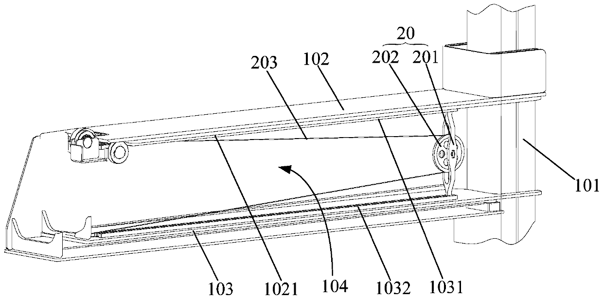
[0044] Such as figure 1 As shown, the embodiment of the first aspect of the present invention provides a telescopic outrigger 1 , including a outrigger assembly and a movable roller assembly 20 . The leg assembly includes a vertical leg 101, an outer leg 102 connected to the vertical leg 101 and an inner leg 103 located inside the outer leg 102 and connected to the vertical leg 101, the inner leg 103 defines a Mounting cavity 104; movable roller assembly 20 comprises the roller bracket 201 that is arranged in the mounting cavity and the movable roller 202 that is arranged on the roller bracket 201, and movable roller 202 is used for winding cable; Wherein, the upper wall surface of mounting cavity 104 and / or Or the lower wall surface is provided with a sliding part, and the roller bracket 201 is provided with a sliding fitting part, and the sliding fitting part cooperates with the sliding part, so that the movable roller assembly 20 is suitable for reciprocating sliding relati...

Embodiment 2

[0048] Embodiment 2 (not shown in the figure)

[0049] The difference from Embodiment 1 is that the sliding part includes an upper guide hole and a lower guide hole, the upper guide hole and the lower guide hole are respectively arranged on the upper wall surface and the lower wall surface of the installation cavity 104, and extend along the length direction of the inner leg 103 respectively The sliding fitting part includes an upper guide column and a lower guide column, the upper guide column and the lower guide column are respectively arranged on the upper end and the lower end of the roller bracket 201, and the upper guide column and the lower guide column are respectively inserted in the upper guide hole and the lower guide hole .

[0050] The sliding part includes an upper guide hole and a lower guide hole respectively arranged on the upper wall surface and the lower wall surface of the installation cavity 104, and the upper guide hole and the lower guide hole are respec...

Embodiment 3

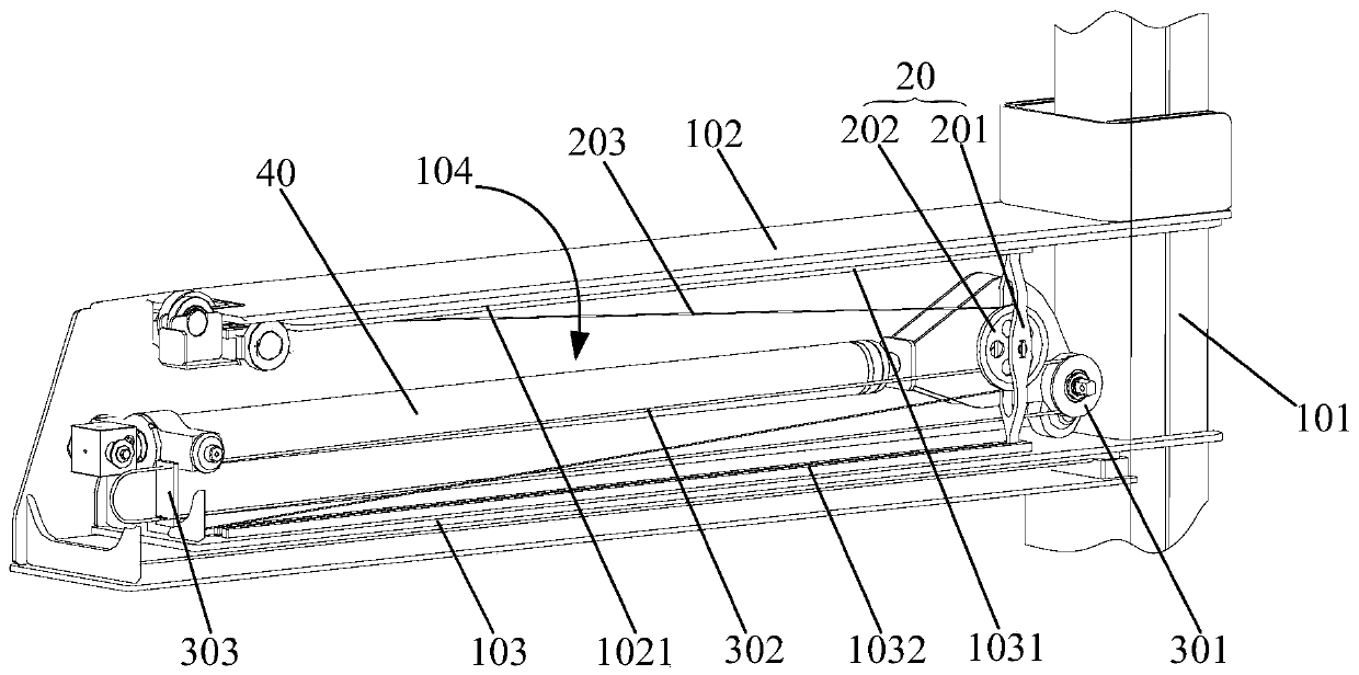
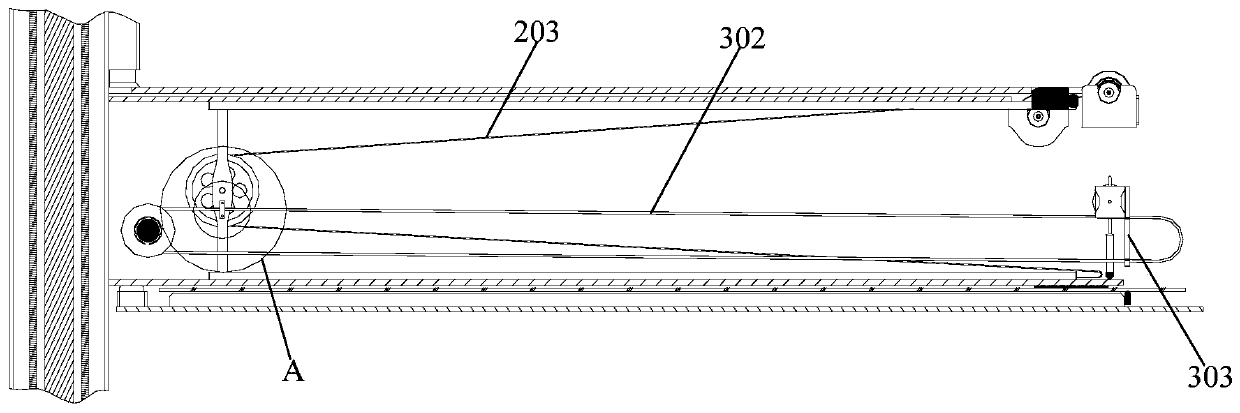
[0058] Such as figure 2 and image 3 As shown, the difference from Embodiment 2 is that the driving mechanism includes: a cable roller 301, which is arranged at one end of the outrigger assembly close to the movable roller assembly 20, and is relatively fixed with the outer outrigger 102; On the cable roller 301, and fixedly connected with the roller bracket 201; the front cable fixing seat 303 is arranged on the end of the leg assembly away from the cable roller 301, and is relatively fixed with the outer leg 102, and the front cable fixing seat 303 is used for The cable 302 is locked or unlocked by cooperating with the locking member; wherein, when the cable 302 is in an unlocked state and the cable 302 is driven, the cable 302 can drive the movable roller assembly 20 to slide back and forth relative to the inner leg.

[0059] The driving mechanism includes a cable roller 301, a cable 302 and a front cable fixing seat 303, wherein the cable roller 301 is arranged on the le...


PUM


Abstract

The invention provides a telescopic supporting leg and a vehicle. The telescopic supporting leg comprises: a supporting leg assembly, wherein the supporting leg assembly comprises a vertical supporting leg, an outer supporting leg connected with the vertical supporting leg, and an inner supporting leg which is located at the inner side of the outer supporting leg and is connected with the verticalsupporting leg, and the inner supporting leg defines an installation cavity; and a movable rolling wheel assembly comprising a rolling wheel support arranged in the mounting cavity and a movable rolling wheel arranged on the rolling wheel support, wherein the movable rolling wheel is used for winding a cable. A sliding part is arranged on the upper wall surface and/or the lower wall surface of the mounting cavity, the rolling wheel support is provided with a sliding fit part, and the sliding fit part is matched with a sliding part, so that the movable rolling wheel assembly is suitable for reciprocating sliding relative to the inner supporting leg. When a cable is replaced and maintained, other structures do not need to be disassembled, only the movable rolling wheel assembly needs to bedriven to slide to the proper position, operation is easy and fast, the replacement and maintenance efficiency of the cable is effectively improved, manpower and material resources are saved, and themaintenance cost is reduced.

Description

technical field [0001] The invention relates to the technical field of vehicles, in particular to a telescopic outrigger and a vehicle including the telescopic outrigger. Background technique [0002] The telescopic outrigger is an auxiliary device widely used in construction machinery. During the construction process, the outriggers are stretched out to support the ground to increase the support span, thereby increasing the stability of the construction machinery. When the outriggers are not working, the outriggers are retracted. Thereby ensuring the passability of the equipment in various roads and construction environments. There are usually sensing, early warning and other components installed on the outriggers, so there is a need for wiring harness connections. In order to ensure that the wiring harness adapts to the telescopic movement of the outriggers, it is necessary to use corresponding telescopic outriggers to prevent interference and friction between the wiring h...

Claims


Application Information

Patent Timeline
IPC IPC(8): B60S9/12B60R16/02
CPCB60R16/0215B60S9/12
Inventor 邓楚飞李文斌万昌雄
Owner SANY AUTOMOBILE MFG CO LTD
Why Eureka
Try Eureka