Roll type strip unwinding device

A technology of unwinding device and strip, which is applied in the direction of winding strip, transportation and packaging, thin material handling, etc., can solve the problems of low work efficiency, damage to strip rolls, easy occurrence of safety accidents, etc., and achieve smooth unwinding. , The strip is straight and the work is reliable.

Pending Publication Date: 2022-05-20
KUNMING DINGCHENG TECH
View PDF0 Cites 0 Cited by
  • Summary
  • Abstract
  • Description
  • Claims
  • Application Information

AI Technical Summary

Problems solved by technology

Obviously, not only is the operation complicated, time-consuming and labor-intensive, and the work efficiency is low, but also it is prone

Method used


Image

  • Roll type strip unwinding device
  • Roll type strip unwinding device

Examples


Example Embodiment

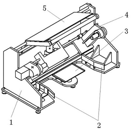
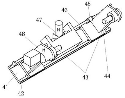
[0014] The roll-type strip unwinding device provided by the present invention comprises a base 1, which is provided with an unwinding mechanism 4, and the unwinding mechanism 4 includes a base plate 41, a slide rail 42 arranged on the base plate 41, and a slide rail 42 sliding seat 44 that is fitted, rotates the unwinding shaft 43 that is fixed on the upper end of the sliding seat 44 by the belt seat bearing, and drives the screw assembly that the sliding seat 44 and the unwinding shaft 43 on the sliding seat 44 move, such as figure 1 ;

[0015] The slide 44 and the unwinding shaft 43 on it are oppositely arranged with two, one of which is connected to the reel motor 48 after the outer end of the unwinding shaft is extended to form an active unwinding shaft, and the two unwinding shafts 43 are respectively placed on two sides of the strip reel. In the cylinder hole at the end, so that the active unwinding shaft and the other unwinding shaft 43 drive the strip coil to rotate sy...


PUM


Abstract

The invention provides a roll type strip unwinding device which comprises a base and is characterized in that an unwinding mechanism is arranged on the base and comprises a bottom plate, a sliding rail arranged on the bottom plate, a sliding seat connected with the sliding rail in a sliding fit mode, an unwinding shaft rotationally fixed to the upper end of the sliding seat through a plummer block, and a lead screw assembly driving the sliding seat and the unwinding shaft on the sliding seat to move. The automatic unwinding device can conveniently support, clamp and center strip coils, automatically unwind, automatically rectify deviation and automatically adjust the width to meet the unwinding requirements of the strip coils with different breadths, is conveniently seamlessly connected with or compatible with previous equipment through the guide positioning device and the jacking platform to prepare for automatic unwinding, and is simple in structure, convenient to operate and low in cost. The device is simple in structure, reliable and stable in work and smooth in unwinding, ensures that the unwound strip is straight, and provides guarantee for subsequent strip processing.

Description

technical field [0001] The invention relates to an unwinding device, in particular to a roll-type strip unwinding device, which belongs to the technical field of design and manufacture of reconstituted tobacco leaf processing equipment. Background technique [0002] In printing, packaging and other industries, before the coiled strip is processed, the strip needs to be pulled out from the strip coil by an unwinding device, flattened and sent to the subsequent processing equipment. The existing unwinding device is to directly put the strip coil on an inflatable shaft. Since the inflatable shaft is at a certain height from the ground, when installing the strip coil, many people are required to cooperate to lift the strip coil to the level of the air shaft. The height of the expansion shaft is the same, or the strip coil is lifted to the same height as the air shaft by the manual operation auxiliary device, so that the strip coil can be placed on the air shaft. Obviously, not ...

Claims


Application Information

Patent Timeline
IPC IPC(8): B65H16/06B65H16/10B65H23/26
CPCB65H16/06B65H16/103B65H23/26
Inventor 高贤杰何贤励潘能翔王文赋刘坤
Owner KUNMING DINGCHENG TECH
Why Eureka
Try Eureka