Pyrolysis device

A pyrolysis and preheating box technology, applied in lighting and heating equipment, combustion types, incinerators, etc., can solve the problems of difficult to achieve large-scale pyrolysis work, simple equipment, and low efficiency.

Active Publication Date: 2020-04-28
北京京能清洁能源电力股份有限公司北京分公司 +1
View PDF10 Cites 1 Cited by
  • Summary
  • Abstract
  • Description
  • Claims
  • Application Information

AI Technical Summary

Problems solved by technology

However, the existing thermal decomposition devices are simple in equipment an

Method used


Image

  • Pyrolysis device
  • Pyrolysis device
  • Pyrolysis device

Examples


Embodiment Construction

[0032] In order to more clearly understand the above objects, features and advantages of the present invention, the present invention will be further described in detail below in conjunction with the accompanying drawings and embodiments. It should be understood that the described embodiments are some, not all, embodiments of the present invention. The specific embodiments described here are only used to explain the present invention, but not to limit the present invention. All other embodiments obtained by those skilled in the art based on the described embodiments of the present invention belong to the protection scope of the present invention.

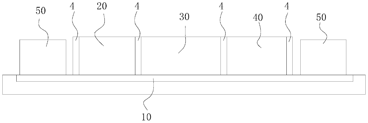
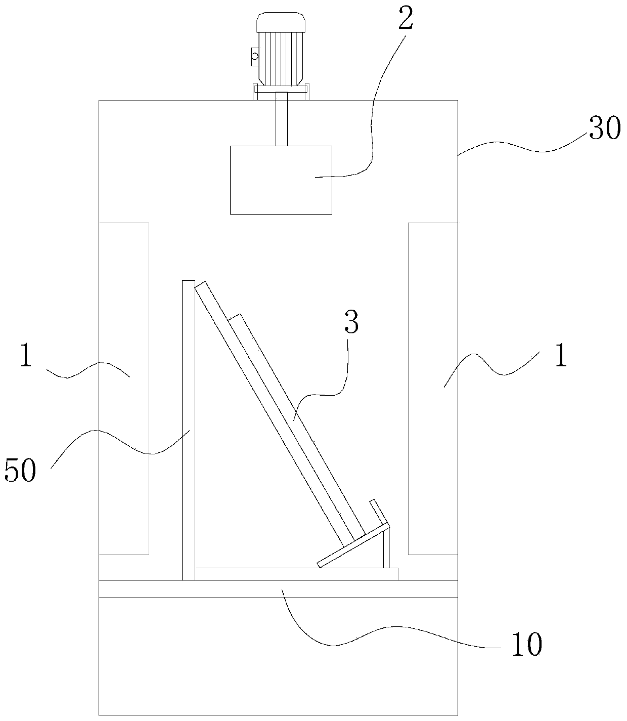
[0033] refer to figure 1 , The present embodiment provides a pyrolysis device, including: a conveying system 10, a preheating box 20, a pyrolysis box 30, a cooling box 40, and a loading device 50; the preheating box 20, the pyrolysis box 30, and the cooling box 40 connected, and are all arranged on the conveying system 10, the con...


PUM


Abstract

The invention provides a pyrolysis device. The pyrolysis device comprises a conveying system, a preheating box, a high temperature decomposition box, a cooling box and loading devices; the preheatingbox, the high temperature decomposition box and the cooling box communicate in sequence and are all arranged on the conveying system; the conveying system can convey the loading devices to enter the preheating box, the high temperature decomposition box and the cooling box in sequence; the loading devices are used for bearing pyrolyzed pieces; a heating piece is arranged in each of the preheatingbox, the high temperature decomposition box and the cooling box; an openable/closable airtight door is arranged at each of an inlet of the preheating box, the position between the preheating box and the high temperature decomposition box, and an outlet of the cooling box; and the airtight door is used for closing the preheating box, the high temperature decomposition box and the cooling box. Through the scheme, the overflow of gases in various areas is effectively partitioned by matching separated heating areas and the airtight doors; the hazard of the overflow of high temperature toxic exhaust gas is prevented; continuous mass production can be realized; and moreover, the production capacity can be adjusted by adjusting the length of each heating area.

Description

technical field [0001] The invention relates to the field of crystalline silicon photovoltaic modules, in particular to a pyrolysis device. Background technique [0002] Crystalline silicon photovoltaic modules are the mainstream products in the photovoltaic market at present. The service life of photovoltaic modules is generally 20-30 years. At present, the modules put into use around 2000 have begun to enter the retirement period. At the same time, due to various quality and use reasons, there are also quite large quantities. There are obsolete components, and as time goes by, the number of decommissioned components will enter an explosive period. A large number of waste components need to be harmlessly treated and resource recycled. [0003] Crystalline silicon photovoltaic modules are generally composed of crystalline silicon solar cells, ribbons, EVA, backplanes, glass, junction boxes, aluminum frames and other materials and components, the main part of which is compos...

Claims


Application Information

Patent Timeline
IPC IPC(8): F23G5/02F23G5/027F23G5/08F23G5/44
CPCF23G5/02F23G5/027F23G5/08F23G5/444F23G5/44F23G2201/30F23G2900/50213Y02W30/82
Inventor 樊立云王学孟姚振宇韩会丽祁娜欧舜杰张存峰谷金达
Owner 北京京能清洁能源电力股份有限公司北京分公司
Why Eureka
Try Eureka