
Water-proof connector

A technology of waterproof connectors and connectors, which is applied in the direction of connection, parts of connection devices, electrical components, etc.

Inactive Publication Date: 2003-06-04
SUMITOMO WIRING SYST LTD
View PDF0 Cites 1 Cited by
  • Summary
  • Abstract
  • Description
  • Claims
  • Application Information

AI Technical Summary

Problems solved by technology

[0005] However, the insertion of the stopper 3C into the mounting hole 2A causes the protrusion 3B to elastically bend, which creates a large resistance when inserted.

Method used


Image

  • Water-proof connector
  • Water-proof connector
  • Water-proof connector

Examples


Embodiment Construction

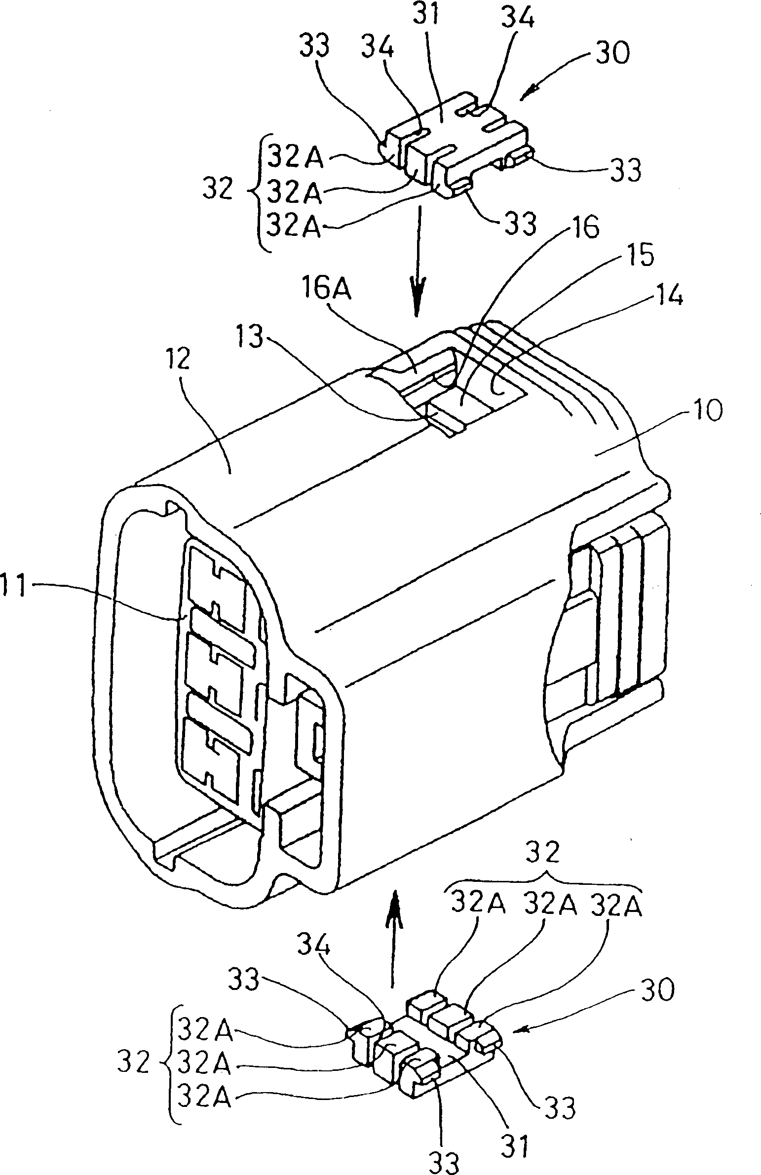
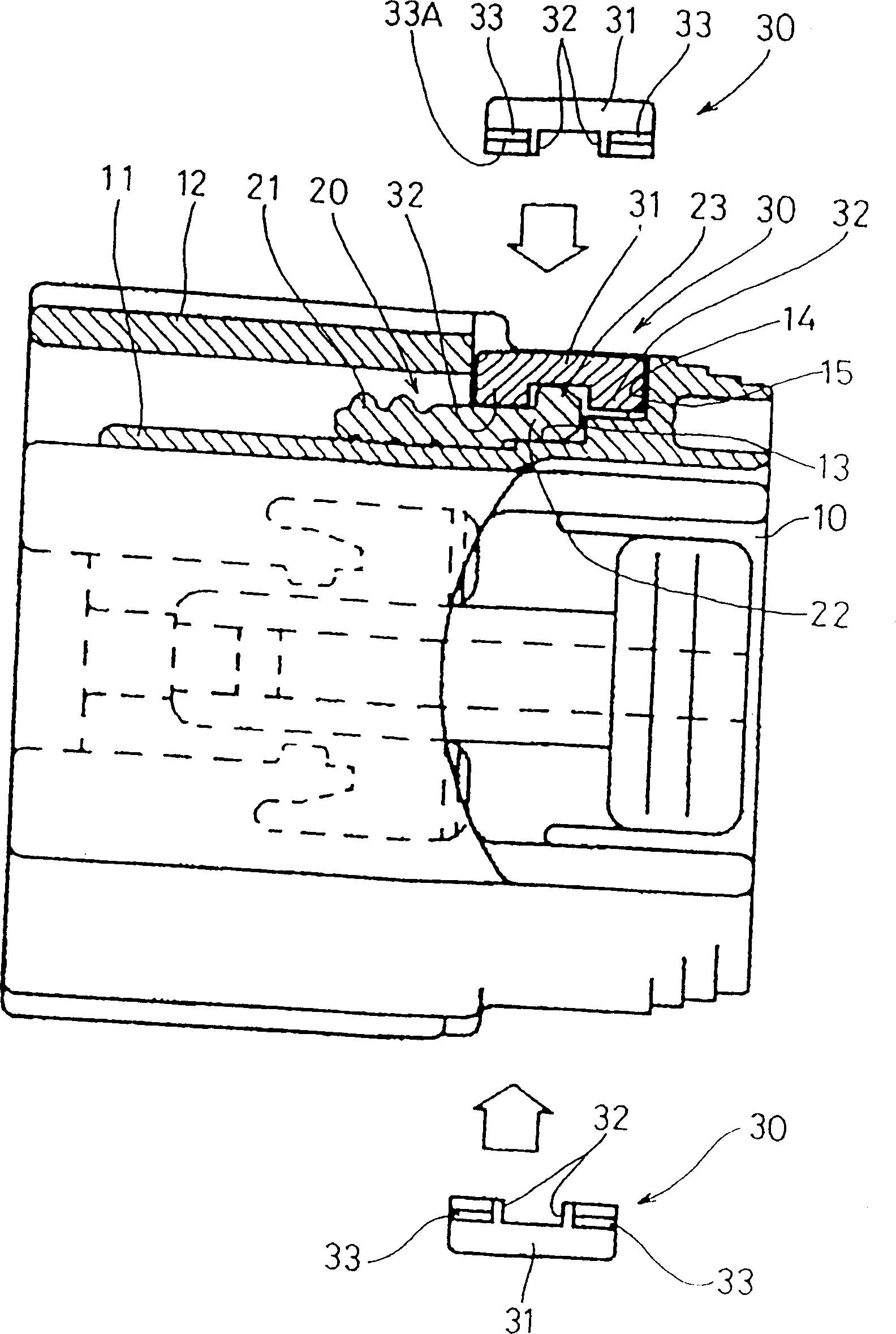
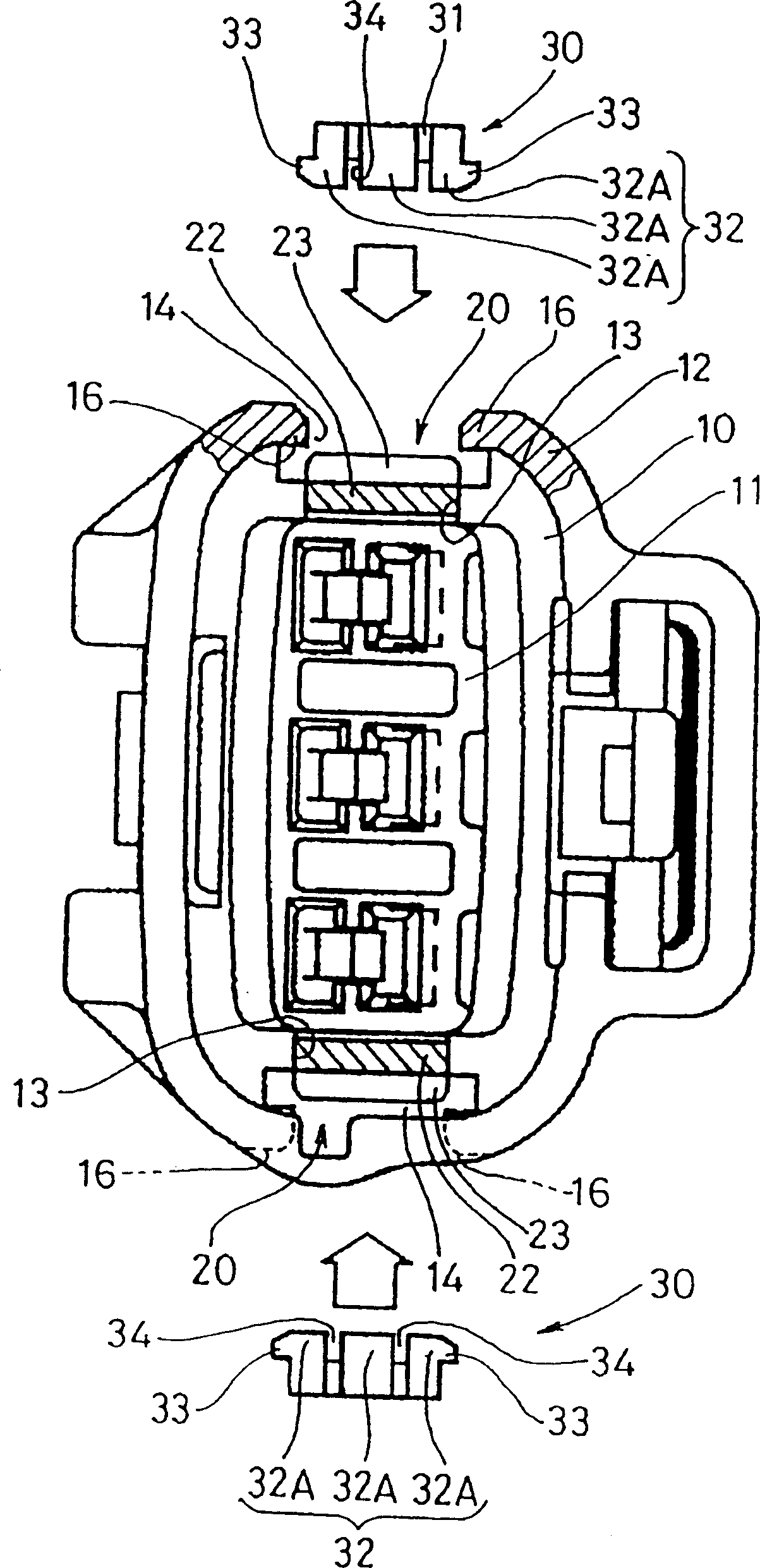
[0028] refer to Figures 1 to 7 , the first embodiment of the present invention will be described below. The preferred embodiment of the waterproof connector includes a female connector housing 10, a male connector housing inserted into the female connector housing 10 (in Figures 1 to 7 not shown in the prior art Figures 8 to 10 Similar to that in ), the sealing member 20 installed in the female connector housing 10 , the clamping member 30 installed in the female connector housing 10 .

[0029] The female connector housing 10 is provided with a housing body 11 and a conduit 12 surrounding the housing body 11 . When the female connector housing 10 is engaged with the male connector housing, a cap (not shown) of the male connector housing slides to the inside of the conduit 12 and is fixed in the housing body 11 . The gap between the inner ring side of the cap and the outer ring side of the housing body (similar to prior art Figure 9 , the gap between the cap 1A and the f...


PUM


Abstract

The present invention provides a waterproof connector, wherein, a clamping part is formed independently from a concave connector crust and can be installed inside the concave connector crust. Before the clamping part is installed, a sealing part is installed inside the concave connector crust. The sealing part comprises a protrudent part which is provided with a gripping part, and the protrudent part is not bended to be inserted into the guide slot of the concave connector crust. Then, the clamping part is installed inside the concave connector crust, two protrudent parts of the clamping part are jointed with the gripping part on the opposite sides, therefore, the sealing part is clamped and can not fall off. When the sealing part is installed, the protrudent part and the gripping part can not produce elastic deformation, which reduces the installation resistance and can realize the installation conveniently.

Description

technical field [0001] The invention relates to a waterproof connector, more specifically to an improvement to the installation structure of a sealing member with waterproof performance. Background technique [0002] A kind of waterproof connector disclosed in the prior art, such as Figures 8 to 10 shown. The connector is provided with a waterproof performance by installing a sealing member at a certain part thereof. Such as Figure 8 The connector shown comprises a male connector 1 , a female connector 2 and a seal 3 . Such as Figure 10 As shown, the sealing member 3 is configured as an annular sealing body 3A, which also includes a mounting protrusion 3B protruding from the sealing body 3A. The sealing body 3A is mounted by fixing the mounting protrusion 3B in the mounting hole 2A of the female connector 2 . When the male connector 1 is inserted into the female connector 2, the cap 1A of the male connector will be fixed in the sealing body 3A...

Claims


Application Information

Patent Timeline
IPC IPC(8): H01R13/52
CPCH01R13/5219
Inventor 松下靖生山下和纪藤谷光弘
Owner SUMITOMO WIRING SYST LTD
Learn More