Automobile panel die

A technology for automobile cover parts and molds, which is applied to forming tools, manufacturing tools, metal processing equipment, etc., can solve the problems of unstable fixing of punches, easy influence on relative limit, etc., and achieve stable limit fixation and easy quick disassembly and assembly. , easy to use effect

Inactive Publication Date: 2020-05-05
扬州市品冠体育用品有限公司
View PDF1 Cites 0 Cited by
  • Summary
  • Abstract
  • Description
  • Claims
  • Application Information

AI Technical Summary

Problems solved by technology

[0004] The purpose of the present invention is to solve the problem that the vibration force generated during the upper and lower stamping work in the prior art can easily affect the relative limit of the L-shaped swing rod to the L-shaped insertion rod, and thus easily cause the problem of unstable fixation of the punch problem, and a kind of automobile panel mold proposed

Method used


Image

  • Automobile panel die
  • Automobile panel die
  • Automobile panel die

Examples


Embodiment Construction

[0019] The following will clearly and completely describe the technical solutions in the embodiments of the present invention with reference to the accompanying drawings in the embodiments of the present invention. Obviously, the described embodiments are only some, not all, embodiments of the present invention.

[0020] In describing the present invention, it should be understood that the terms "upper", "lower", "front", "rear", "left", "right", "top", "bottom", "inner", " The orientation or positional relationship indicated by "outside", etc. is based on the orientation or positional relationship shown in the drawings, and is only for the convenience of describing the present invention and simplifying the description, rather than indicating or implying that the referred device or element must have a specific orientation, so as to Specific orientation configurations and operations, therefore, are not to be construed as limitations on the invention.

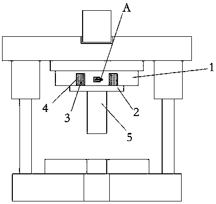
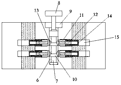
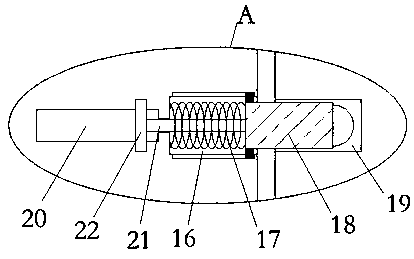
[0021] refer to Figure ...


PUM


Abstract

The invention discloses an automobile panel die which comprises a lower die holder. A transversely-arranged female die fixing plate is arranged on the side wall of the upper side of the lower die holder. A female die is arranged in the female die fixing plate. A through hole is formed in the side wall of the lower die holder and located under the female die. A transversely-arranged upper die holder is arranged above the lower die holder. The upper die holder and the lower die holder are connected through two symmetrically-arranged guide posts and guide sleeves. A transversely-arranged male diecushion plate is arranged on the side wall of the side, away from a die shank, of the upper die holder. A transversely-arranged male die fixing plate is arranged on the side wall of the side, away from the upper die holder, of the male die cushion plate. A locating plate is arranged on the lower side of the male die fixing plate. Two locating blocks are symmetrically and fixedly connected to theupper end of the locating plate. Locating grooves corresponding to the locating blocks are formed in the lower end of the male die fixing plate. The lower end of the locating plate is fixedly connected with a male die. By the adoption of the automobile panel die, the male die can be quickly detached and installed conveniently and can be more stably limited and fixed.

Description

technical field [0001] The invention relates to the technical field of moulds, in particular to an automobile cover mould. Background technique [0002] Automobile panels are auto parts that make up the car body or cab, cover the surface and interior of the special-shaped body of the engine and chassis. During the repeated stamping process of the automobile panel mold, the punch will wear out. Therefore, it is necessary to timely The worn punch is replaced, and when the punch is replaced by the existing mold, the operation is relatively cumbersome, time-consuming and labor-intensive. [0003] After searching, the patent authorization announcement number is CN 207839809 U, which proposes a kind of automobile panel mould, including a lower mold base, the upper side wall of the lower mold base is provided with a horizontally arranged concave mold fixing plate, and the concave Die fixed plate is provided with die, the side wall of described lower mold base is provided with thro...

Claims


Application Information

Patent Timeline
Patent Type & Authority Applications(China)
IPC IPC(8): B21D37/04
CPCB21D37/04
Inventor 不公告发明人
Owner 扬州市品冠体育用品有限公司
Why Eureka
Try Eureka