Implant for medical use intended to clip to a biological protuberance

An implant, biological technology, applied in the direction of application, medical science, surgery, etc.

Active Publication Date: 2020-05-05
DIANOSIC
View PDF10 Cites 0 Cited by
  • Summary
  • Abstract
  • Description
  • Claims
  • Application Information

AI Technical Summary

Problems solved by technology

So it is not suitable for keeping in place for a long time (for example, several months)

Method used


Image

  • Implant for medical use intended to clip to a biological protuberance
  • Implant for medical use intended to clip to a biological protuberance
  • Implant for medical use intended to clip to a biological protuberance

Examples


Embodiment Construction

[0029] In the following description, elements will be described with reference to an orthogonal reference frame formed by the longitudinal direction L, the vertical direction V, and the transverse direction T. As shown in FIG.

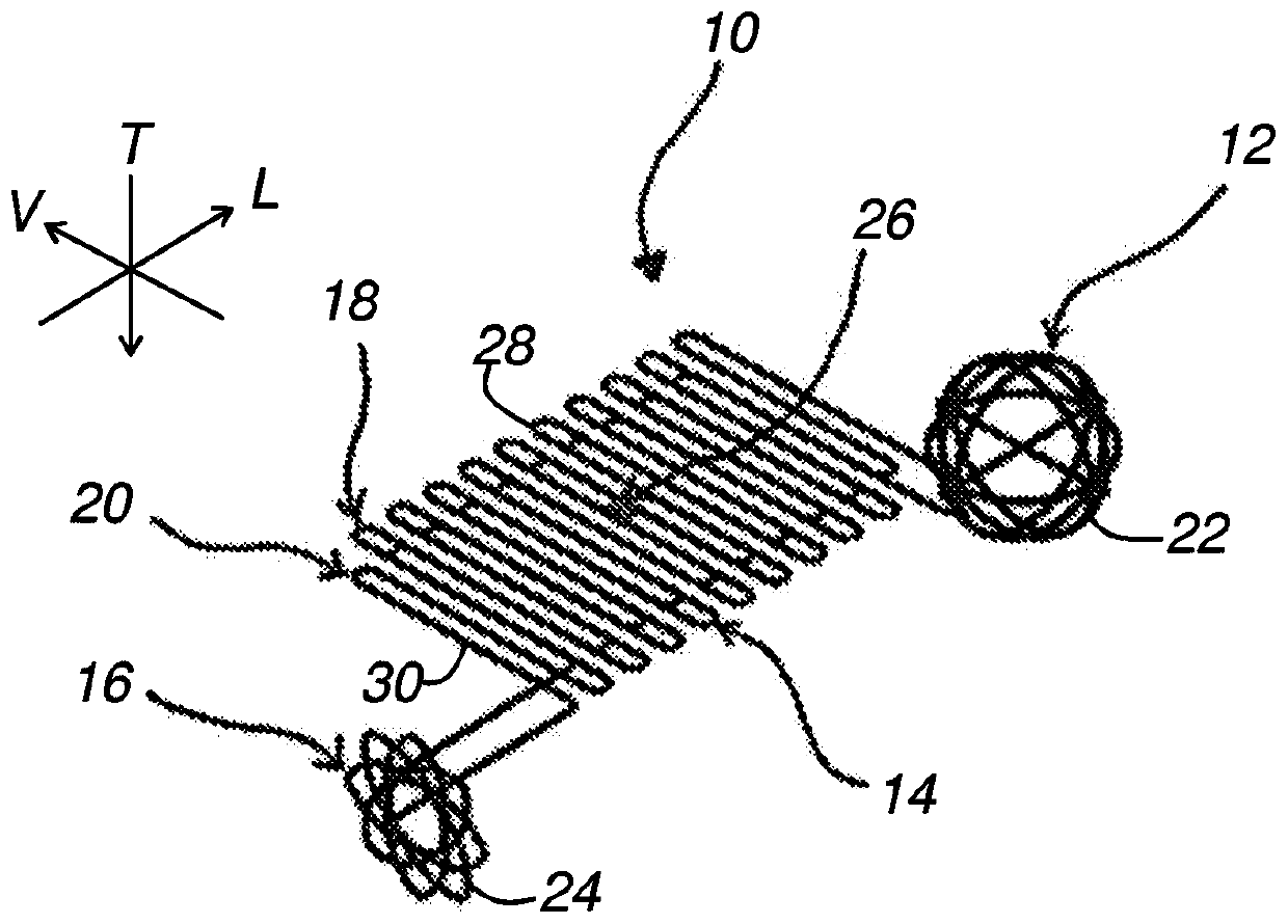
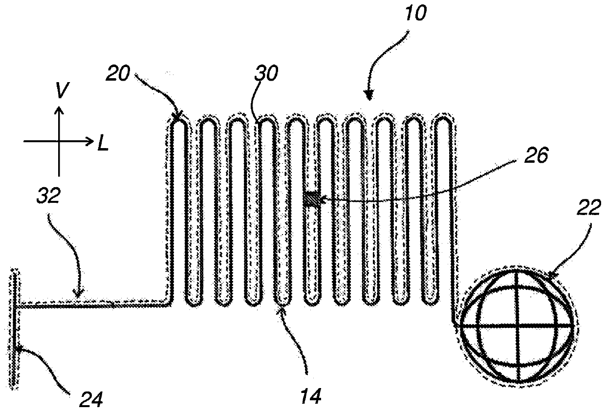
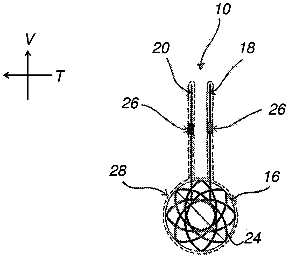
[0030] exist Figure 1 to Figure 4 The implant 10 for medical use according to the first embodiment of the present invention, shown schematically in an unfolded state in Part 12.

[0031] The central part 14 is intended to clamp on biological protrusions present in the cavity of the human or animal body. For this purpose, the central part 14 comprises two wall parts 18 , 20 extending substantially facing each other and serving to clamp the bioprotrusion between the two wall parts. Each wall portion 18 , 20 has a lower edge attached to the anterior portion 16 and the posterior portion 12 of the implant 10 . In the example described, the two wall portions 18 , 20 are planar and extend parallel to the plane defined by the longitudinal direction and the ...


PUM


Abstract

This implant (70) is intended to be introduced into a human or animal body cavity, and comprises two walls intended to grip between them a biological protuberance present in the cavity in order to attach the implant (70) to the biological protuberance. Each wall comprises a structural element (76, 78; 84, 86) having corrugations such that the structural element (76, 78; 84, 86) is folded up on itself several times, enabling the wall (76, 78; 84, 86) to be folded up before the introduction of the implant (70), then deployed inside the cavity.

Description

technical field [0001] The present invention relates to an implant for medical use which is clamped at biological protrusions. [0002] More particularly, the invention applies to implants for medical use intended to be introduced into cavities of the human or animal body, the implant comprising at least one clamp comprising two wall parts, the two wall parts For clamping the bio-protrusion present in the cavity between these two walls in order to attach the implant to the bio-protrusion. Background technique [0003] Such an implant is described in US Patent Application Publication No. US 2013 / 0276794 A1. It is used to protect the middle turbinate during nasal surgery. Therefore, the implant is only required for surgical procedures. So it is not suitable for keeping in place for a long time (for example, several months). [0004] Accordingly, it may be desirable to provide an implant for medical use which allows overcoming at least some of the above-mentioned problems a...

Claims


Application Information

Patent Timeline
Patent Type & Authority Applications(China)
IPC IPC(8): A61B90/00A61B17/24
CPCA61B17/24A61B2017/00867A61B2090/064A61B90/08A61B2090/0816A61B5/002A61B2505/05A61B5/686A61B5/6867A61B2560/0406A61B90/04A61B2017/00004A61B2017/00889A61B2017/00893
Inventor M·奥古斯汀P·巴斯泰德
Owner DIANOSIC
Why Eureka
Try Eureka