A kind of anti-counterfeiting printing equipment

A technology of anti-counterfeiting printing and equipment, which is applied in the direction of spray device, device for coating liquid on the surface, liquid spray device, etc., can solve the problems of low efficiency, failure of anti-counterfeiting operation of coating and scraping winning prizes, etc., to achieve efficient printing and covering, and increase work efficiency , The effect of the simple structure of the device

Active Publication Date: 2021-11-23
SHANDONG TAIBAO PREVENTING COUNTERFEIT
View PDF4 Cites 0 Cited by
  • Summary
  • Abstract
  • Description
  • Claims
  • Application Information

AI Technical Summary

Problems solved by technology

[0002] Anti-counterfeiting printing equipment is not only aimed at the orientation of currency, but also anti-counterfeiting for some commodity packaging that prevents counterfeiting and shoddy products. The existing anti-counterfeiting printing equipment has many shortcomings. It is mainly aimed at the fact that it is easy for personnel to imitate the printing process of scratch-coated paper, and to manufacture similar prize-winning paper. The general problem is that the printing smear layer and the anti-translucent layer are carried out in a separate process, which makes it easier for personnel to know the batch Scratch paper winning situation, and use non-winning counterfeit paper to replace the winning paper, which makes the anti-counterfeiting work of scratch winning invalid, and due to the use of separate processes for operations, it also makes the scratch-winning paper The time efficiency is low, and the existing equipment cannot better adjust the situation that the scratching layer covers the winning area, so that it is easier for personnel to know the winning situation of the paper

Method used


Image

  • A kind of anti-counterfeiting printing equipment
  • A kind of anti-counterfeiting printing equipment
  • A kind of anti-counterfeiting printing equipment

Examples


Embodiment Construction

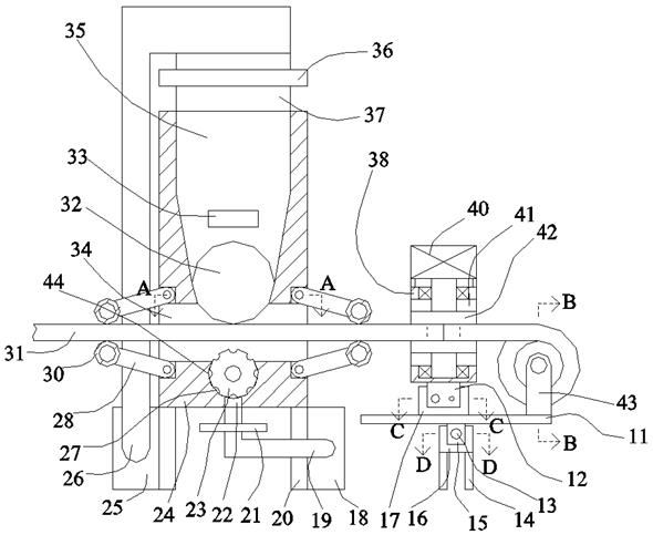
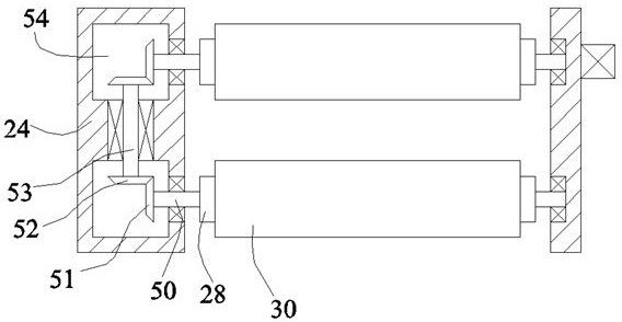
[0024] Such as Figure 1-Figure 5 As shown, the present invention is described in detail. For the convenience of description, the orientations mentioned below are now stipulated as follows: figure 1The up, down, left, right, front and back directions of the projection relationship itself are consistent. An anti-counterfeiting printing device of the present invention includes a side box 24. A penetrating through cavity 34 is arranged inside the side box 24. The lower end surface of the side box 24 is fixed There are symmetrical support feet 20, the two sides of the support feet 20 are respectively fixed with a liquid storage tank 25 and a storage tank 18, and a storage inner cavity 35 located in the side box 24 is arranged above the through cavity 34, so that The storage inner cavity 35 is communicated with the through cavity 34, so that the upper side of the storage inner cavity 35 is communicated with a bottom side connecting pipe 37, and the bottom side connecting pipe 37 is...


PUM


Abstract

The invention discloses an anti-counterfeiting printing device, which comprises a side box body. A penetrating cavity is arranged in the side box body. Symmetrical support feet are fixed on the lower end surface of the side box body. The two sides of the support feet are fixed respectively. A liquid storage tank and a storage tank are provided, and a storage inner cavity located in the side box is arranged above the through cavity, and the storage inner cavity is communicated with the through cavity, so that the upper side of the storage inner cavity is communicated. There is a bottom-side connecting pipe, and a top-side valve body is communicated in the bottom-side connecting pipe, and a vertical pipe is arranged between the top-side valve body and the liquid storage tank, and the vertical pipe connects the liquid storage tank. The tank is connected to the valve body on the top side. The device of the present invention has a simple structure. This device adopts the design of the scratch-coating layer and the anti-translucent layer, which can print and cover the winning paper efficiently, and can adjust the effect of the scratch-coating layer and the anti-translucent layer on the The coverage of the winning area increases the working efficiency of the equipment and improves the anti-counterfeiting technical level of the winning paper.

Description

technical field [0001] The invention relates to the technical field of printing equipment, in particular to an anti-counterfeiting printing equipment. Background technique [0002] Anti-counterfeiting printing equipment is not only aimed at the orientation of currency, but also anti-counterfeiting for some commodity packaging that prevents counterfeiting and shoddy products. The existing anti-counterfeiting printing equipment has many shortcomings. It is mainly aimed at the fact that it is easy for personnel to imitate the printing process of scratch-coated paper, and to manufacture similar prize-winning paper. The general problem is that the printing smear layer and the anti-translucent layer are carried out in a separate process, which makes it easier for personnel to know the batch Scratch paper winning situation, and use non-winning counterfeit paper to replace the winning paper, which makes the anti-counterfeiting work of scratch winning invalid, and because the operati...

Claims


Application Information

Patent Timeline
Patent Type & Authority Patents(China)
IPC IPC(8): B05C1/12B05C1/08B05C13/02B05B9/03
CPCB05B9/03B05C1/0808B05C1/0813B05C1/0821B05C1/12B05C13/02
Inventor 储小英
Owner SHANDONG TAIBAO PREVENTING COUNTERFEIT
Why Eureka
Try Eureka