Hanging Basket System for Prefabricated Beam Erection
A technology of prefabricated beams and main trusses, applied in the direction of bridge construction, erection/assembly of bridges, bridges, etc., can solve problems such as inconvenience of fixing, and achieve the effect of easy use, less cumbersome process, and simple operation.
- Summary
- Abstract
- Description
- Claims
- Application Information
AI Technical Summary
Problems solved by technology
Method used
Image
Examples
Embodiment 1
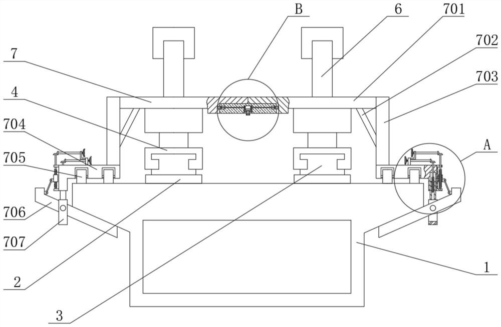
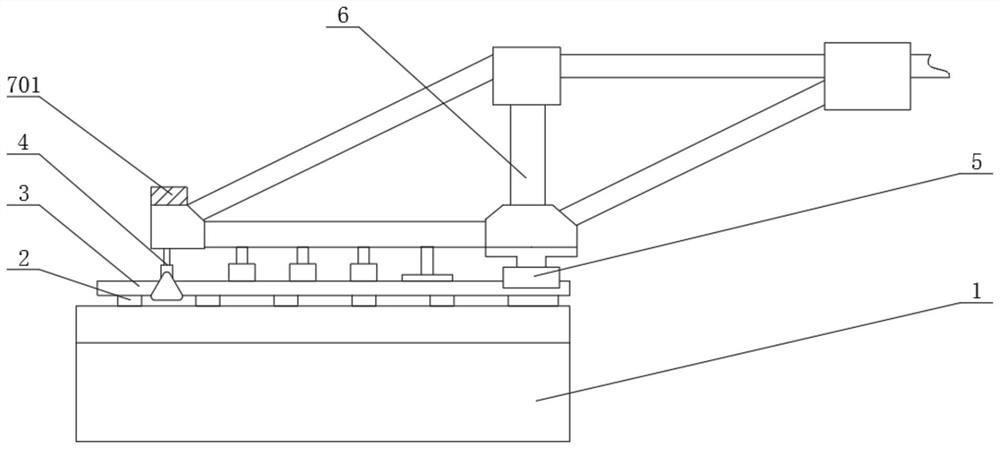
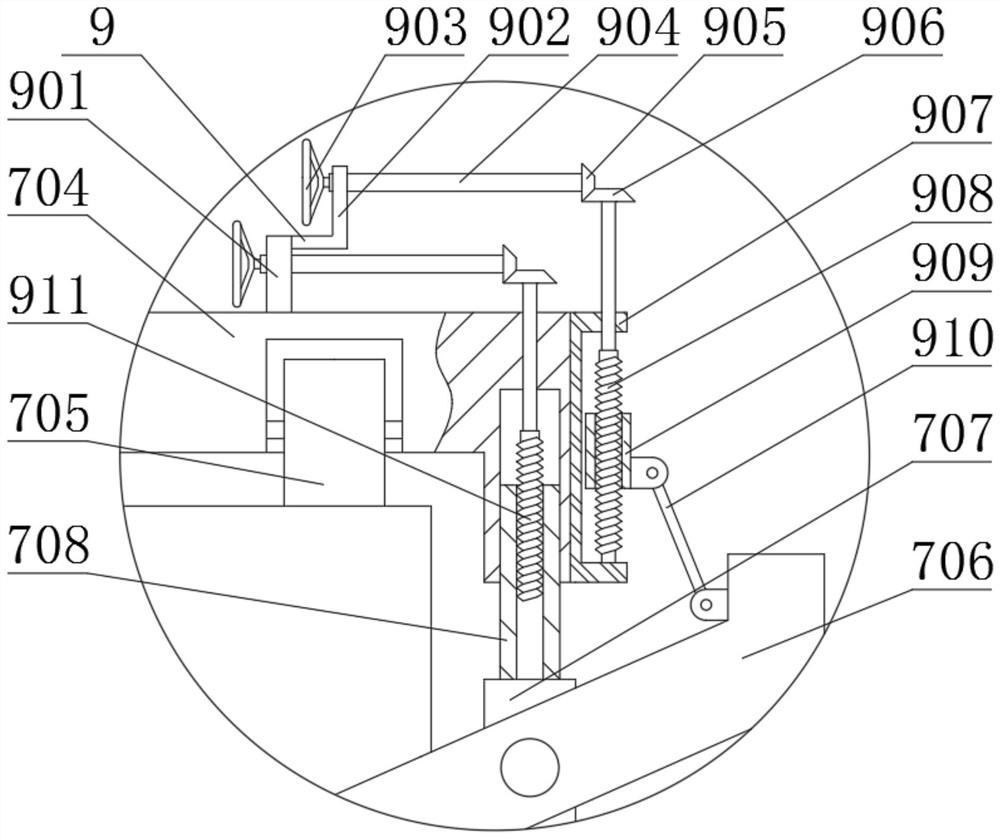
[0030] see Figure 1-6 , the present invention provides a technical solution:
[0031] The hanging basket system for erecting prefabricated beams includes construction body 1 and track pad beam 2, the top of construction body 1 is fixedly connected with track pad beam 2, the top of track pad beam 2 is fixedly connected with track 3, and the outside of track 3 is provided with anti Buckle 4, the front support 5 is fixedly connected to the rear side of the top of the track 3, the top of the reverse buckle 4 is fixedly connected to a diamond-shaped main truss 6, and the top of the diamond-shaped main truss 6 is fixedly connected to a longitudinal limit device 7, and the longitudinal limit The device 7 is connected with a connecting device 8 at the center and an adjusting device 9 at both ends. The longitudinal limiting device 7 includes a pressure beam plate 701, a reinforcing beam 702, a vertical beam 703, a crossbeam 704, a roller 705, a limiting plate 706, a fixed The frame 7...
Embodiment 2
[0038] In Embodiment 2, the same parts as in Embodiment 1 will not be repeated. The difference is that when the connecting plate 801 needs to be removed from the top of the pressure beam plate 701 on the left and right sides, the staff turns the bolt 805 counterclockwise with a wrench , drive the ring gear 806 to rotate through the bolt 805, then the ring gear 806 drives the first bevel gear 807 to rotate, then the first bevel gear 807 drives the screw 802 to rotate through the connecting shaft 808, and drives the limit block 803 to approach the gear ring 806 through the screw 802 Move in the direction of the vertical centerline until the stop block 803 separates from the draw-in groove on the inside of the pressure beam plate 701, then stop turning the bolt 805, and the connecting plate 801 can be taken off.
PUM
 Abstract
Description
Claims
Application Information
 - R&D
- Intellectual Property
- Life Sciences
- Materials
- Tech Scout
- Unparalleled Data Quality
- Higher Quality Content
- 60% Fewer Hallucinations
Browse by: Latest US Patents, China's latest patents, Technical Efficacy Thesaurus, Application Domain, Technology Topic, Popular Technical Reports.
© 2025 PatSnap. All rights reserved.Legal|Privacy policy|Modern Slavery Act Transparency Statement|Sitemap|About US| Contact US: help@patsnap.com


