
Data transmission method and network equipment

A technology for a data transmission method and network equipment, applied in the field of data transmission methods and network equipment, capable of solving problems affecting quality of service, accumulation of target packet transmission delay, etc.

Active Publication Date: 2020-05-08
CHINA UNITED NETWORK COMM GRP CO LTD
View PDF5 Cites 1 Cited by
  • Summary
  • Abstract
  • Description
  • Claims
  • Application Information

AI Technical Summary

Problems solved by technology

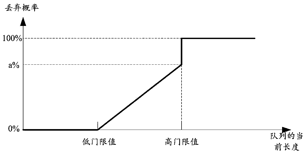
[0005] After research, when the above-mentioned technology is used to send the message from the network device to the next-hop device, there will be the following problems: After the network device receives the target message, it will determine the QoS priority of the target message according to the QoS priority of the target message. The target queue corresponding to the message; then cache the target message in the target queue to wait for processing
In this way, the transmission delay of the target message will continue to accumulate, which may eventually affect the service quality of the service to which the target message belongs.

Method used


Image

  • Data transmission method and network equipment
  • Data transmission method and network equipment
  • Data transmission method and network equipment

Examples


Embodiment 1

[0048] Based on the foregoing technical principle, an embodiment of the present application provides a data transmission method, and the method is applied to a first network device. Wherein, the first network device may specifically include transmission nodes in various types of transmission networks. For example, the first network device can be Figure 4 One of the transmission nodes A, B, C, D, E, F, G, H in the transmission network shown. For example, the first network device may be an electronic device such as a switch or a router.

[0049] Exemplarily, when the first network device is a router, Figure 5 It is a schematic structural diagram of a first network device provided in this application. Wherein, the first network device 100 includes a plurality of interface boards 101 (specifically including an interface board 101 a , an interface board 101 b . . . an interface board 101 n in the figure), a switching fabric board 102 and a main control board 103 . Each of the...

Embodiment 2

[0170] An embodiment of the present application provides a network device, configured to implement the data transmission method performed by the first network device in the first embodiment above. Such as Figure 13 As shown in , it is a schematic diagram of a possible structure of the network device provided by the embodiment of the present application. Specifically, the network device 400 includes: an acquiring unit 401 , a packet generating unit 402 , and a sending unit 403 . in:

[0171] An acquisition unit 401, configured to acquire a target message; the target message includes a first priority field, and the first priority field is used to indicate the QoS priority of the target message;

[0172] The message generating unit 402 is configured to generate a remark message when the length of the target queue is detected to reach a preset threshold value; wherein, the target queue includes: in the first network device, according to the Qos priority of the target message T...

Embodiment 3

[0215] The embodiment of the present application also provides a computer-readable storage medium, the computer-readable storage medium includes instructions; when the instructions are run on the network device, the network device is made to execute the method provided in the embodiment of the present application.

[0216] The embodiment of the present application also provides a computer program product including computer instructions, which, when running on the network device, enables the network device to execute the method provided in the embodiment of the present application.


PUM


Abstract

The invention provides a data transmission method and network equipment, and relates to the field of communication. According to the invention, the situation that the target message is congested continuously at a plurality of transmission nodes in the transmission path in the transmission process can be avoided as much as possible. The method comprises the steps of acquiring a target message; andwhen it is detected that the length of the target queue reaches a preset threshold value, generating a re-marked message, wherein the service data carried by the remarked message is the same as that carried by the target message, the remarked message comprises a second priority field used for indicating the Qos priority of the remarked message, and the Qos priority indicated by the second priorityfield is higher than the Qos priority indicated by the first priority field, the target queue comprises a queue which corresponds to the target message and is determined according to the Qos priorityof the target message in first network equipment; and sending the remarked message to second network equipment in response to the generation of the remarked message. The method is applied to data transmission.

Description

technical field [0001] The present application relates to the communication field, and in particular to a data transmission method and network equipment. Background technique [0002] With the development of information technology, new services and new application scenarios emerge in an endless stream, which leads to an increasingly large data traffic in the communication network. Furthermore, the problem of network congestion has gradually become one of the common reasons leading to the degradation of network service quality. [0003] Currently, a common method to control network congestion is as follows: [0004] When a device interface in a network device is congested, the packets to be processed by the device interface are buffered first, and then the buffered packets are sequentially sent to corresponding subsequent devices by the device interface. Wherein, when the message is cached, the message will be allocated to a queue corresponding to the message in multiple qu...

Claims


Application Information

Patent Timeline
IPC IPC(8): H04L12/801H04L12/851H04L12/863H04L12/927H04L47/80
CPCH04L47/12H04L47/24H04L47/805H04L47/2433H04L47/2408H04L47/50H04L47/803
Inventor 韩博文刘畅王泽林何晓峰
Owner CHINA UNITED NETWORK COMM GRP CO LTD
Learn More