Variable gain amplification circuit for pressure-sensitive touch control

A gain amplification circuit and touch technology, applied in the direction of gain control, amplification control, electrical components, etc., can solve the problems of current consumption, unfriendly data processing, power consumption, cost increase, etc.

Pending Publication Date: 2020-05-12
SHENZHEN STATE MICRO TECH CO LTD
View PDF0 Cites 0 Cited by
  • Summary
  • Abstract
  • Description
  • Claims
  • Application Information

AI Technical Summary

Problems solved by technology

[0006] (1) For the input, the input resistance is R1, because the touch network cannot drive the resistive load, which directly affects the input voltage;
[0007] (2) The operational amplifier needs to drive a resistive load, which requires continuous consumption of additional current;
[0008] (3) When the input is zero, the output bias voltage changes with the gain configuration, which is easy to cause output saturation, and it is not friendly to the subsequent signal or data processing after ADC conversion, and the gain cannot be switched arbitrarily during use;
[0009] (4) The problem can be solved by using a negative power supply, but the power consumption and cost will also increase
[0011] That is to say, when VIN=0, VOUT=VB, when it is necessary to configure different output bias voltages at zero input, it is necessary to change the VB voltage value, but this requires that the input range of the operational amplifier is large enough, and may be used depending on requirements Only rail-to-rail operational amplifiers can cover the full bias voltage range, which increases the complexity and difficulty of operational amplifier design

Method used


Image

  • Variable gain amplification circuit for pressure-sensitive touch control
  • Variable gain amplification circuit for pressure-sensitive touch control
  • Variable gain amplification circuit for pressure-sensitive touch control

Examples


Embodiment Construction

[0031] In order to make the object, technical solution and advantages of the present invention more clear, the present invention will be further described in detail below in conjunction with the accompanying drawings and embodiments. It should be understood that the specific embodiments described here are only used to explain the present invention, not to limit the present invention.

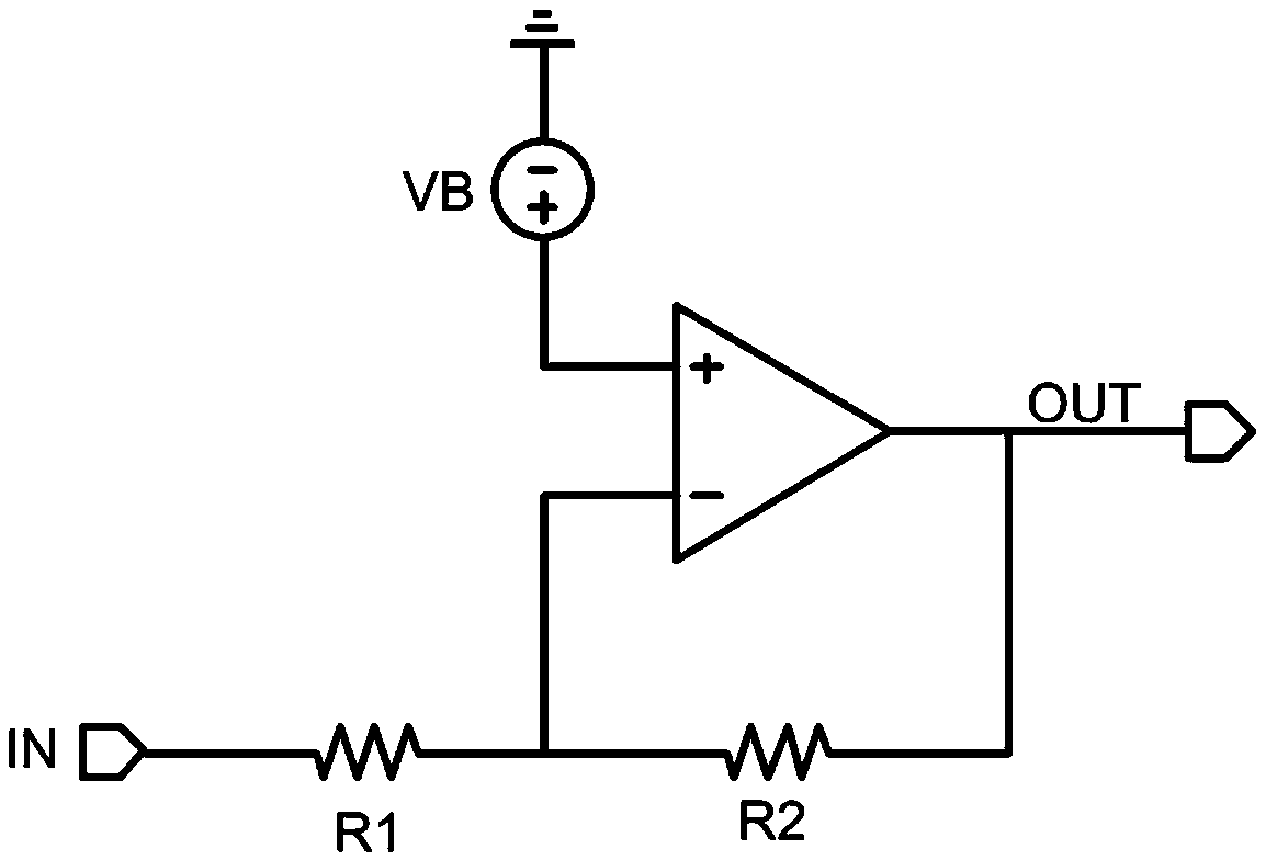
[0032] The invention mainly solves the disadvantages of the prior art, and provides a design that does not require the input voltage range of the operational amplifier, changes the gain without affecting the output bias point, and obtains an output signal that is only related to the reference voltage, gain and input.

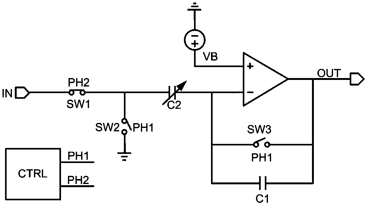
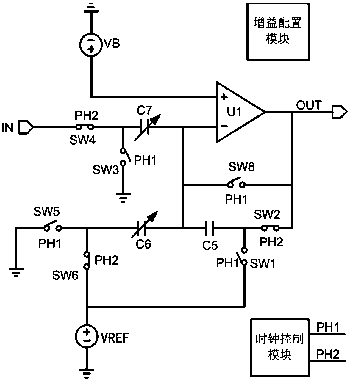
[0033] The invention discloses a variable gain amplifier circuit for pressure-sensitive touch, which includes an operational amplifier module, a gain configuration module, and a clock control module, wherein the clock control module is used to generate a control clock; the gain con...


PUM


Abstract

The invention discloses a variable gain amplification circuit for pressure-sensitive touch. The circuit comprises an operational amplification module, a gain configuration module and a clock control module; the clock control module is used for generating a control clock; the gain configuration module is used for configuring gain and output bias voltage according to the control signal, so that an input signal is amplified through reverse operation, superposed with fixed bias voltage and then output; according to the invention, the gain of the amplification circuit is adjusted by adjusting the capacitance value ratio of the input end of an operational amplifier to a feedback branch; the fixed bias amount of the output voltage is changed by adjusting the capacitance value ratio of the input of the operational amplifier to a reference voltage branch; the output signal is only related to the reference voltage, the gain and the input, accurate amplification is obtained when the voltage of the input signal is close to zero, and the problem in amplification when the input signal is close to zero (ground) during light touch in a pressure-resistance change-voltage sensing-based touch schemeis solved.

Description

technical field [0001] The invention relates to a signal amplifying circuit, in particular to a variable gain amplifying circuit based on a pressure-sensitive touch array composed of force-sensitive materials when the input signal to the ground is close to zero when the pressure is small. Background technique [0002] The pressure sensing network based on high-sensitivity force-sensitive materials can be applied in the design of human-computer interaction. The circuit of the pressure-sensing grid of force-sensitive materials is equivalent to a pressure variable resistor. This resistance-based touch solution It has the advantages of anti-electromagnetic interference, waterproof, anti-oil pollution, foldable and easy to expand, which are not available in capacitive touch solutions. [0003] The voltage characteristic of the output signal of the sensor network equivalent to a variable resistance network is that the greater the pressure, the higher the voltage output, and when n...

Claims


Application Information

Patent Timeline
Patent Type & Authority Applications(China)
IPC IPC(8): H03G3/20H03G3/00H03K17/96
CPCH03G3/008H03G3/20H03K17/9645
Inventor 唐飞球黄国勇陈杰鲁金梅
Owner SHENZHEN STATE MICRO TECH CO LTD
Why Eureka
Try Eureka