Supercharge Your Innovation With Domain-Expert AI Agents!

Method and device for correcting rgb-ir images

An RGB-IR, RGB image technology, applied in the field of image processing, can solve the problems of affecting the use effect, the large volume of the infrared filter device, and the change of the focal length.

Active Publication Date: 2021-11-05
ASR SMART TECH CO LTD
View PDF7 Cites 0 Cited by
  • Summary
  • Abstract
  • Description
  • Claims
  • Application Information

AI Technical Summary

Problems solved by technology

[0005] However, the infrared filter device based on the mechanical structure is large in size, which will cause the focal length to change and affect the clarity of the image; and it is expensive; when assembled in mobile devices such as mobile phones, daily collisions will easily cause displacement and affect the use effect

Method used


Image

  • Method and device for correcting rgb-ir images
  • Method and device for correcting rgb-ir images
  • Method and device for correcting rgb-ir images

Examples


Embodiment Construction

[0044] see figure 2 , an embodiment of the RGB-IR image correction method provided by this application includes the following steps.

[0045] Step S10: Input an RGB-IR image.

[0046] Step S20: Perform black level correction on the input RGB-IR image. The dark level refers to the magnitude of dark current.

[0047] Step S30: Perform gain compensation on the IR components according to each color channel.

[0048] Step S40: Calculate the residual of the RGB components of each color channel minus the IR component after gain compensation, and obtain the minimum residual, and then calculate the correction coefficient of the IR component according to the minimum residual.

[0049] Step S50: Correct the RGB components according to the correction coefficients of the IR components and the IR components after gain compensation and output them.

[0050] Further, in the step S10, the RGB-IR image includes two parts: an RGB image and an IR image. see image 3 , the RGB image is dist...


PUM


Abstract

The present application discloses a method for correcting RGB-IR images, which includes the following steps. Step S10: Input RGB-IR image. Step S20: Perform dark level correction on the input RGB-IR image. Step S30: performing gain compensation on the IR component according to each color channel. Step S40: Calculate the residual after subtracting the gain-compensated IR component from the RGB components of each color channel, and obtain the minimum residual, and then calculate the correction coefficient of the IR component according to the minimum residual. Step S50: Correct and output the RGB components according to the correction coefficient of the IR component and the IR component after gain compensation. This application realizes the correction of RGB-IR images through image processing, and adaptively removes or retains part or all of the infrared components in the bright and dark areas of the image, so that the two indicators of image brightness and image non-color cast strike a balance.

Description

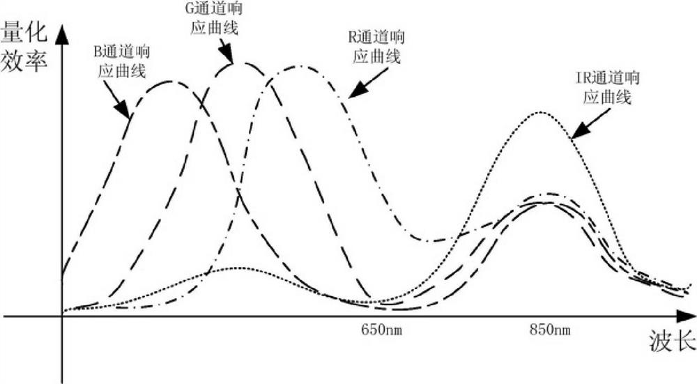
technical field [0001] The present application relates to the field of image processing, and in particular, to a method and apparatus for processing image data. Background technique [0002] With the development of multimedia technology, the camera function of devices such as video surveillance and mobile phones has been paid more and more attention by users. The photographing functions of the above-mentioned devices are all realized based on the image sensor. When the user takes a photograph during the day when the light is sufficient, the image sensor can receive enough light, and then the image can be clearly imaged. However, when the light is insufficient at night, the image sensor cannot take pictures properly, and the range of use of these devices will be limited. [0003] In order to solve the problem of taking pictures in low-light scenes, the image sensor will receive some near-infrared (NIR, Near-infrared) as a supplement to visible light. But if figure 1 As sho...

Claims


Application Information

Patent Timeline
Patent Type & Authority Patents(China)
IPC IPC(8): H04N5/361H04N9/04
CPCH04N25/63H04N23/841
Inventor 史汉臣李成军
Owner ASR SMART TECH CO LTD
Features
  • R&D
  • Intellectual Property
  • Life Sciences
  • Materials
  • Tech Scout
  • Unparalleled Data Quality
  • Higher Quality Content
  • 60% Fewer Hallucinations
Learn More