
Connecting mechanism for moving part of three-dimensional statue

A technology for connecting mechanisms and moving mechanisms, applied in the field of stage machinery, can solve the problems of simple activities, no visual appreciation, disorder, etc., and achieve the effect of stable assembly relationship

Active Publication Date: 2020-05-22
ZHEJIANG DAFENG IND
View PDF3 Cites 4 Cited by
  • Summary
  • Abstract
  • Description
  • Claims
  • Application Information

AI Technical Summary

Problems solved by technology

But the existing movable three-dimensional statue can only complete the action of simple translation and closing, and also only when the three-dimensional statue is in the closed state, it can give the audience a visual statue display. Parts are disordered and do not give people a visual appreciation
Therefore, there are generally problems in the existing movable three-dimensional statues that the activities are simple and only have the outline of the statue in the closed state, and the display effect is poor.

Method used


Image

  • Connecting mechanism for moving part of three-dimensional statue
  • Connecting mechanism for moving part of three-dimensional statue
  • Connecting mechanism for moving part of three-dimensional statue

Examples


Embodiment 1

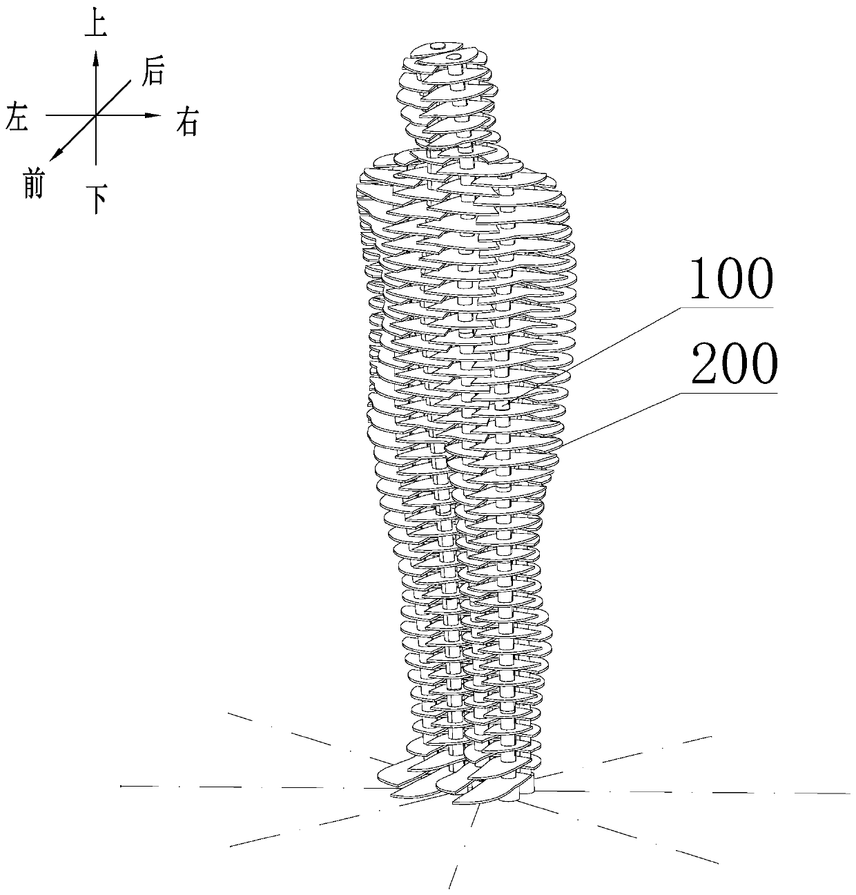
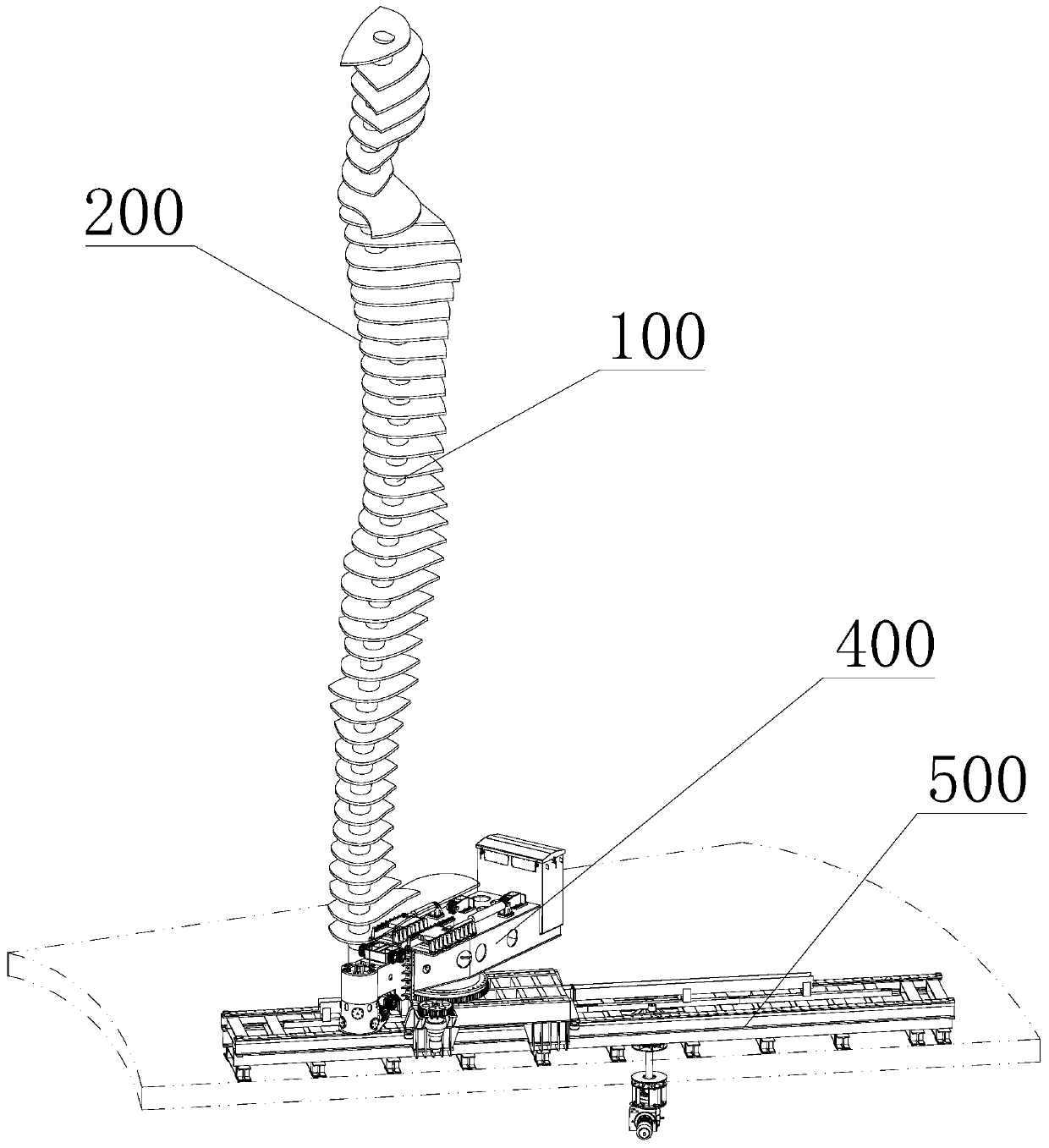
[0048] Such as image 3 As shown, the blade unit 200 in the above-mentioned three-dimensional statue includes a plurality of blades 201 , all the blades 201 are set outside the column 100 , and each blade 201 is arranged at intervals in sequence along the length direction of the column 100 . At least one blade 201 or all blades 201 of the above-mentioned all blades 201 include a blade body 2011 and a support ring 2012 for carrying the blade body 2011. The support ring 2012 is sleeved outside the column 100 and connected to the column 100. The blade The main body 2011 is installed on the support ring 2012, and the blade main body and the support ring 2012 are rotated along the axial limit of the column 100 along the circumferential direction of the column 100. The blade motor 301 rotating on the support ring 2012 , that is, the blade main body 2011 is rotated by the blade motor 301 in the blade driving unit 300 . Of course, the conventional driving components such as a hydraul...

Embodiment 2

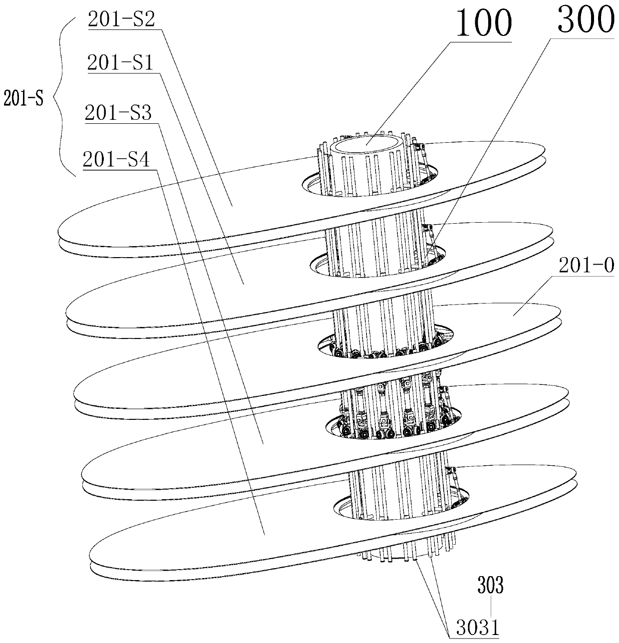
[0055] The basic structure is the same as that of Embodiment 1, the difference is: as Figure 3-9 As shown, the number of blades 201 on the above-mentioned single column 100 is N, and all the N blades 201 are sequentially divided into M groups of blade groups, where N is an integer greater than 2, and M is an integer less than N and greater than 1 . And the number of blades 201 included in the M group of blade groups is greater than 2. The blade group is composed of at least one reference blade 201-0 and at least one movable blade 201-S, that is, at least one of the blades 201 in the blade group is the reference blade 201 -0, the remaining blades 201 are movable blades 201-S. Taking the blade group consisting of five blades 201 in the M group of blade groups as an example, the blade 201 in the middle position in the blade group is the reference blade 201-0, and the upper part of the reference blade 201-0 is successively arranged with upper One movable blade 201-S1 and the up...

Embodiment 3

[0060] The basic structure is the same as that of Embodiment 2, the difference is: as Figure 14 As shown, the reference blade 201-0 may not be set in the blade group consisting of one or more blades, but a virtual reference plane O is preset, and all the blades 201 in the blade group are uniformly adjusted by the axial movable mechanism 302. Move toward the reference plane O to realize the display effect of gathering to form a flower pattern, or reset the flower pattern from the gathered state to the initial state.

[0061] Especially when the number of blades 201 in a single blade group is an even number, it is impossible to find a reference blade 201-0 in the middle position in the axial direction, so it is necessary to set this reference plane O, and the above reference plane O can be selected along the column 100 The plane on the axis where any point is located in the area corresponding to the blade set.

[0062]As a preference, in consideration of the symmetry of the fo...


PUM


Abstract

The invention discloses a moving part constituting a three-dimensional statue. The moving part comprises stand columns and blade sets arranged on the stand columns, wherein the blade sets comprise reference blades and movable blades which are arranged at intervals in the axial directions of the stand columns, and the reference blades are fixedly connected with the stand columns; and the moving part is characterized in that the movable blades match with the stand columns through supporting rings in a rotating mode, three connecting points are arranged in the circumferential direction of each supporting ring, axial moving mechanisms are arranged at the positions, where the three connecting points are located, of each stand column correspondingly, and each of the three connecting points of each supporting ring are connected with the corresponding axial moving mechanism through one reference connecting piece and two adjustable connecting pieces with the adjustable lengths correspondingly.The invention provides a connecting mechanism for the moving part of the three-dimensional statue, and the connecting mechanism not only enables a statue to be in a contour shape in a gathering stateand a dispersing state, but also enables the moving part to be firmly and reliably connected with the stand columns on the basis of not influencing the movement.

Description

technical field [0001] The invention relates to the technical field of stage machinery, in particular to a connection mechanism for movable parts of three-dimensional statues. Background technique [0002] Three-dimensional statues are an important part of the process of urban humanities construction. There are movable three-dimensional statues in the existing three-dimensional statues, and the three-dimensional statues can be moved according to a predetermined track through driving components, thereby improving the display effect of the three-dimensional statues. But the existing movable three-dimensional statue can only complete the action of simple translation and closing, and also only when the three-dimensional statue is in the closed state, it can give the audience a visual statue display. Parts are disordered and do not give people visual appreciation. Therefore, there are generally problems in the existing movable three-dimensional statues that the movable actions ...

Claims


Application Information

Patent Timeline
Patent Type & Authority Applications(China)
IPC IPC(8): B44C3/06
CPCB44C3/06
Inventor 田海弘王小君徐跃平刘榛尹文敬丁强吴杰军章晓明朱介勇李长辛
Owner ZHEJIANG DAFENG IND
Learn More