

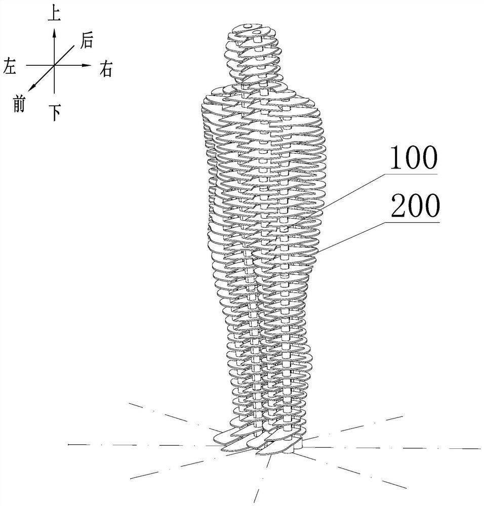
Connection mechanism of movable parts of three-dimensional statue
A technology for connecting mechanisms and movable parts, applied in decorative structures, decorative arts, etc., can solve the problems of simple movement, poor display effect, disorder, etc., and achieve the effect of stable assembly relationship
- Summary
- Abstract
- Description
- Claims
- Application Information
AI Technical Summary
Problems solved by technology
Method used
Image

Examples
Embodiment 1
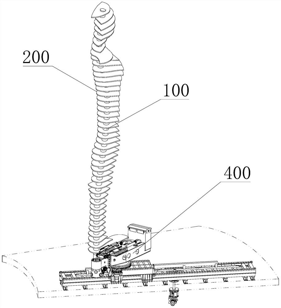
[0048] Such as image 3 As shown, the blade unit 200 in the above-mentioned three-dimensional statue includes a plurality of blades 201 , all the blades 201 are set outside the column 100 , and each blade 201 is arranged at intervals in sequence along the length direction of the column 100 . At least one blade 201 or all blades 201 of the above-mentioned all blades 201 include a blade body 2011 and a support ring 2012 for carrying the blade body 2011. The support ring 2012 is sleeved outside the column 100 and connected to the column 100. The blade The main body 2011 is installed on the support ring 2012, and the blade main body and the support ring 2012 are rotated along the axial limit of the column 100 along the circumferential direction of the column 100. The blade motor 301 rotating on the support ring 2012 , that is, the blade main body 2011 is rotated by the blade motor 301 in the blade driving unit 300 . Of course, the conventional driving components such as a hydraul...
Embodiment 2
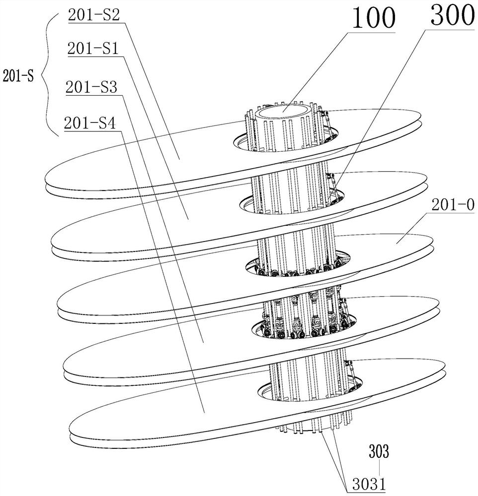
[0055] The basic structure is the same as that of Embodiment 1, the difference is: as Figure 3-9 As shown, the number of blades 201 on the above-mentioned single column 100 is N, and all the N blades 201 are sequentially divided into M groups of blade groups, where N is an integer greater than 2, and M is an integer less than N and greater than 1 . And the number of blades 201 included in the M group of blade groups is greater than 2. The blade group is composed of at least one reference blade 201-0 and at least one movable blade 201-S, that is, at least one of the blades 201 in the blade group is the reference blade 201 -0, the remaining blades 201 are movable blades 201-S. Taking the blade group consisting of five blades 201 in the M group of blade groups as an example, the blade 201 in the middle position in the blade group is the reference blade 201-0, and the upper part of the reference blade 201-0 is successively arranged with upper One movable blade 201-S1 and the up...
Embodiment 3
[0060] The basic structure is the same as that of Embodiment 2, the difference is: as Figure 14 As shown, the reference blade 201-0 may not be set in the blade group consisting of one or more blades, but a virtual reference plane O is preset, and all the blades 201 in the blade group are uniformly adjusted by the axial movable mechanism 302. Move toward the reference plane O to realize the display effect of gathering to form a flower pattern, or reset the flower pattern from the gathered state to the initial state.
[0061]Especially when the number of blades 201 in a single blade group is an even number, it is impossible to find a reference blade 201-0 in the middle position in the axial direction, so it is necessary to set this reference plane O, and the above reference plane O can be selected along the column 100 The plane on the axis where any point is located in the area corresponding to the blade set.
[0062] As a preference, in consideration of the symmetry of the fo...
PUM
 Abstract
Description
Claims
Application Information