Tail puller positioning structure and linear actuator

A positioning structure and positioning surface technology, applied in the direction of electric components, control mechanical energy, electrical components, etc., can solve problems such as troubles, achieve stable positioning effect, long positioning life, and stable assembly relationship

Pending Publication Date: 2018-09-21
ZHEJIANG JIECHANG LINEAR MOTION TECH
View PDF0 Cites 0 Cited by
  • Summary
  • Abstract
  • Description
  • Claims
  • Application Information

AI Technical Summary

Problems solved by technology

[0004] Since the driven objects have many shapes and structures, and the driven objects are installed in the installation groove in a directional way, when the linear actuator drives different driven objects, the circumferential direction of the tail pull needs to be replaced to a certain extent. , the existing method of changing the circumferential direction of the tail pull is usually to disassemble the shell as a whole, and then rotate the tail pull to a certain angle, and then reinstall and fix the shell. This method of reversing requires the disassembly of the entire shell, which is very troublesome

Method used


Image

  • Tail puller positioning structure and linear actuator
  • Tail puller positioning structure and linear actuator
  • Tail puller positioning structure and linear actuator

Examples


Embodiment 1

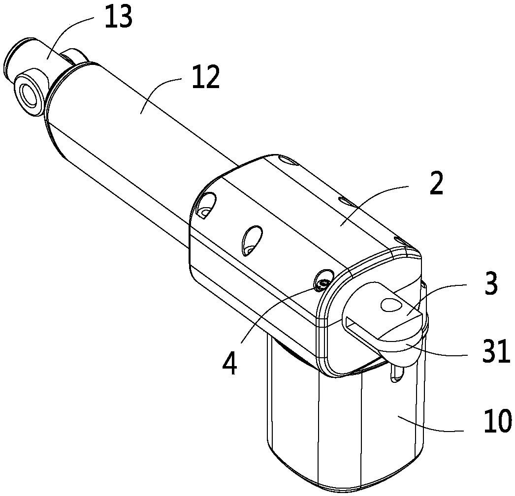
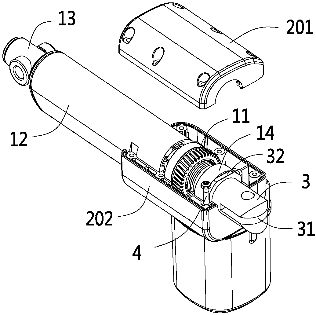
[0030] Such as Figure 1 to Figure 4 As shown, the present embodiment is a linear actuator. The linear actuator in the present embodiment includes a drive motor 10, a drive worm, a worm wheel 11, a screw, and a nut. The drive motor 10 is connected to the drive worm, and the drive worm drives the worm wheel 11 to rotate. , the rotation of the worm wheel 11 drives the screw to rotate, and the rotation of the screw drives the nut to move axially. In addition, this embodiment also includes a shell 2, an outer tube 12, and an inner tube 13. The outer shell 2 is connected to the outer tube 12, and the nut is connected to the inner tube 13 connection, the axial movement of the nut is finally expressed as the axial relative displacement between the inner tube 13 and the outer tube 12 .

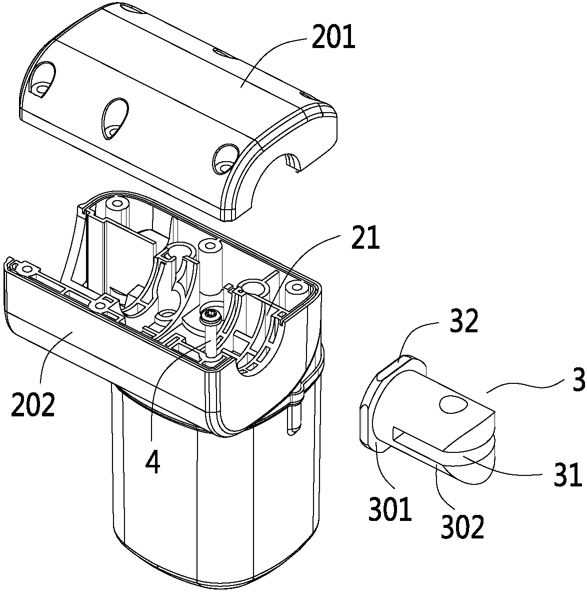
[0031] The linear actuator in this embodiment also includes a tail pull 3, which is provided with a mounting groove 31 for fixing the driven object, and the tail pull 3 is connected with the shell 2 a...

Embodiment 2

[0044] The difference between this embodiment and Embodiment 1 is that the positioning column used to match the positioning surface is not a fastening screw, as for the fastening piece that fixes the first shell and the second shell, it can still be a fastening screw Or other buckle structure.

[0045] The positioning column in this embodiment is a positioning pin, and the positioning pin is inserted into the embedded groove in a plug-in manner. In order to prevent the positioning pin from detaching from the embedded groove, it can be fastened with a buckle, for example, in the embedded A buckle groove is arranged in the loading groove, and an elastic buckle or elastic steel ball is arranged in the positioning pin. When the positioning pin is inserted, the elastic buckle or elastic steel ball cooperates with the buckle groove, and the side of the positioning pin fits and matches with the embedded section 301 simultaneously. Locating pins can be cylindrical pins or square pins ...


PUM


Abstract

The invention discloses a tail puller positioning structure, and belongs to the technical field of linear transmission. The tail puller positioning structure comprises a tail puller and an outer casing, a mounting groove for fixing a driven object is formed in the tail puller, the tail puller is connected with the outer casing and partially protrudes out of the outer casing, the tail puller includes a fitting section, a fitting groove is formed in the outer casing, the fitting section is rotatably installed in the fitting groove, at least two positioning faces are arranged on the outer peripheral side of the fitting section, a positioning post member is mounted on the outer casing, the positioning post member is inserted from the outer casing and at least partially protrudes into the fitting groove, and the side face of the positioning post member is matched with the positioning faces to limit the tail puller in circumferential rotation. The invention further discloses a linear actuator. The tail puller positioning structure has the advantage that the tail puller can be quickly reversed.

Description

【Technical field】 [0001] The invention relates to a tail pull positioning structure, which belongs to the technical field of linear transmission. 【Background technique】 [0002] Linear actuators, also known as electric push rods, are widely used in furniture, medical equipment, solar power generation, etc. The main structure includes a drive motor, a drive worm, a worm wheel, a screw, and a nut. The working principle is that the drive motor drives the drive worm Rotation, the transmission worm meshes with the worm wheel to drive the worm wheel to rotate, the worm wheel to drive the screw to rotate, the screw to rotate to drive the nut to move axially, the nut is generally connected to the inner tube, so as to realize the telescopic movement of the inner tube. [0003] In order to facilitate the connection between the linear actuator and the driven object, the linear actuator usually includes a casing, and the casing is connected with a tail pull. The tail pull in the prior a...

Claims


Application Information

Patent Timeline
IPC IPC(8): H02K7/06
CPCH02K7/06
Inventor 陆小健俞晶连石鑫
Owner ZHEJIANG JIECHANG LINEAR MOTION TECH
Why Eureka
Try Eureka