Oil fume filtering device capable of cooling oil fume

A technology for oil fume filtration and oil fume, which is applied in the removal of oil fume, dispersed particle filtration, transportation and packaging, etc., can solve the problem of low cooling efficiency of oil fume, and achieve the effect of improving cooling efficiency, increasing filtration time and facilitating natural cooling.

Inactive Publication Date: 2020-06-05
金百利科技(深圳)有限公司
View PDF14 Cites 2 Cited by
  • Summary
  • Abstract
  • Description
  • Claims
  • Application Information

AI Technical Summary

Problems solved by technology

[0003] The main purpose of the present invention is to provide an oil fume filter device capable of cooling the oil fume, aiming to solve the technical problem of low efficiency of the existing oil fume filter device in cooling the oil fume

Method used


Image

  • Oil fume filtering device capable of cooling oil fume
  • Oil fume filtering device capable of cooling oil fume

Examples


Embodiment Construction

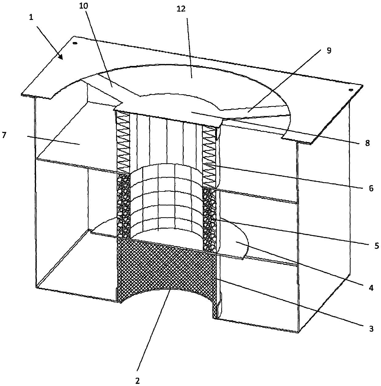
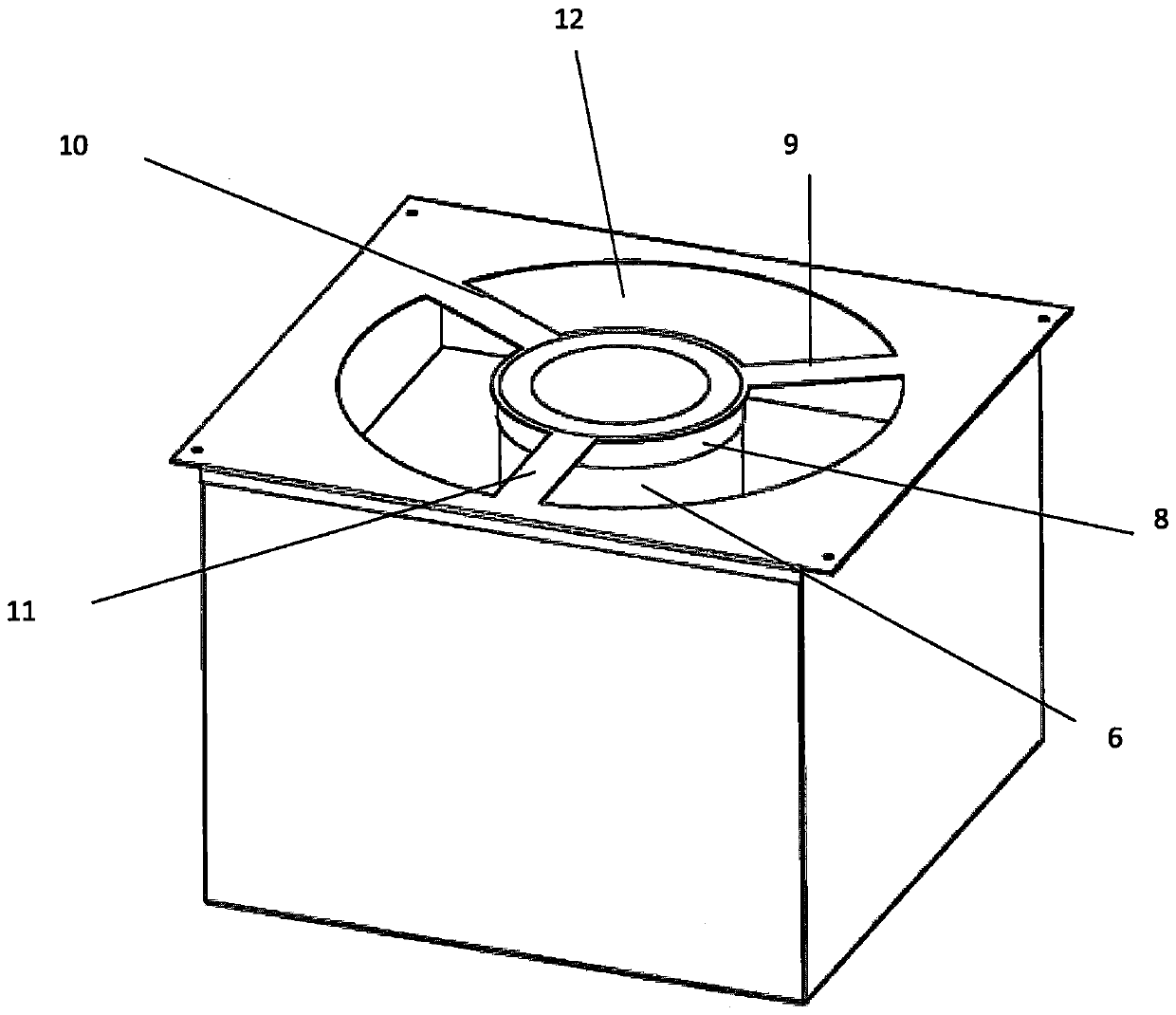
[0012] Embodiments of the present invention are described in detail below, examples of which are shown in the drawings, wherein the same or similar reference numerals designate the same or similar elements or elements having the same or similar functions throughout. The embodiments described below by referring to the figures are exemplary and are intended to explain the present invention and should not be construed as limiting the present invention. In the description of the present invention, it should be understood that the orientation or positional relationship indicated by the terms "inner", "upper", etc. is based on the orientation or positional relationship shown in the drawings, and is only for the convenience of describing the present invention and simplifying the description. It is not intended to indicate or imply that the referred device or element must have a particular orientation, be constructed in a particular orientation, and operate in a particular orientation,...


PUM


Abstract

The invention discloses an oil fume filtering device capable of cooling oil fume, belongs to the technical field of kitchen appliances, and is designed for solving the problem that an existing deviceis poor in oil fume cooling effect. An oil fume collecting cavity is formed in the top of a filtering body, an air inlet hole communicated with the oil fume collecting cavity is formed in the bottom of the filtering body, an air outlet hole communicated with the oil fume collecting cavity is formed in the top of the filtering body, a first exhaust net corresponding to the air inlet hole is arranged in the filtering body, a first partition plate is arranged at the top of the first exhaust net, a second air exhaust net is arranged above the first partition plate, a third air exhaust net is arranged above the second air exhaust net, a second partition plate is arranged between the second air exhaust net and the third air exhaust net, a connecting hole used for communicating the second air exhaust net and the third air exhaust net is formed in the second partition plate, and a third partition plate is arranged at the top of the third air exhaust net. According to the oil fume filtering device capable of cooling oil fume, the oil fume cooling effect is improved.

Description

technical field [0001] The invention relates to the technical field of oil fume filtering devices, in particular to an oil fume filtering device capable of cooling the oil fume. Background technique [0002] At present, the oil fume is generally filtered through the filter screen of the planar structure, and the oil fume directly passes through the oil fume filter layer of the planar structure, so the time for the oil fume to stay in the oil fume filter device is relatively short. Therefore, the oil fume that does not enter the oil fume filter device The difference between the temperature and the temperature of the filtered oil fume flowing out from the oil fume filter device is small. If the filtered oil fume is discharged directly, the temperature of the air outside the oil fume filter device will rise in a short time. As the temperature of the air outside the oil fume filter device rises, the filtered oil fume is generally cooled by an air cooling device such as an air co...

Claims


Application Information

Patent Timeline
Patent Type & Authority Applications(China)
IPC IPC(8): B01D46/00B01D46/24B01D46/42F24C15/20
CPCB01D46/2411B01D46/4218F24C15/2035B01D46/62
Inventor 古俊锋
Owner 金百利科技(深圳)有限公司
Why Eureka
Try Eureka