A telescopic track installation structure and adjustment method at the beam joints of horizontal and vertical curve superimposed sections

A technology of telescopic rail and installation structure, applied in the field of rail engineering, can solve the problems of high risk factor and difficult construction of cross-river bridges, and achieve the effect of satisfying traffic and comfortable riding.

Active Publication Date: 2021-06-01
中铁十五局集团路桥建设有限公司 +1
View PDF6 Cites 0 Cited by
  • Summary
  • Abstract
  • Description
  • Claims
  • Application Information

AI Technical Summary

Problems solved by technology

[0002] The construction of the subway long-span river-crossing bridge is difficult and the risk factor is high

Method used


Image

  • A telescopic track installation structure and adjustment method at the beam joints of horizontal and vertical curve superimposed sections

Examples


Embodiment 1

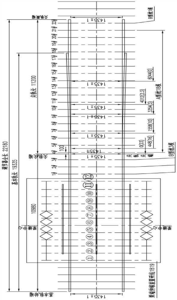
[0036] refer to figure 1 As shown, this embodiment is a telescopic rail installation structure at the beam joints of the horizontal and vertical curve superimposed sections, including beam end telescopic devices and rail telescopic regulators arranged above the bridge joints and on the rail lines on both sides. lie on a horizontal curve and a vertical curve at the same time;

[0037] The center line of the telescopic device at the beam end coincides with the center line of the beam joint;

[0038] The basic rail and the switch rail of the rail telescopic adjuster are respectively installed on both sides of the beam gap, and the basic rail is located on the approach bridge side, and the switch rail is located on the main bridge side;

[0039] The basic rail of the rail telescopic adjuster is fixedly connected with at least one steel sleeper on the approach bridge side of the beam end telescopic device; the rail telescopic adjuster is located outside the main bridge side of the...

Embodiment 2

[0046] This embodiment is a method for adjusting the telescopic track at the beam joint of the superimposed horizontal and vertical curves, which can be used for the track installation structure in Example 1. The steps of the adjustment method include:

[0047] Place the telescopic device at the beam end within the preset position range on the concrete beam surface at the beam joint;

[0048] Lift the telescopic device at the beam end to the design elevation, and adjust the center line and lateral position to the predetermined position;

[0049] The beam end telescopic device is fixed by the rail support frame, the tool rail on the beam end telescopic device is removed, the basic rail of the rail telescopic adjuster is connected with at least one steel sleeper on the approach bridge side of the beam end telescopic device, and the rail telescopic adjustment The basic rail of the device is located on the side of the approach bridge, and the point rail is located on the side of t...

Embodiment 3

[0064] The following uses a specific application example to illustrate the installation structure and adjustment method. refer to figure 1 For example, the bridge joint of a horizontal and vertical curve section is 800mm, the planned track line is on a curve with a radius of 2000m, and the curve is also on a vertical curve with a radius of 3550m.

[0065] Utilize the present invention to carry out the design of installation structure such as figure 1 , The telescopic device at the beam end includes 12 steel sleepers ①-⑫, of which 3 steel sleepers ⑤-⑦ are suspended above the beam joints. The basic rail of the rail telescopic regulator faces the approach bridge side, the tip rail faces the main bridge side, the rails of the basic rail are connected to the steel sleepers of the telescopic devices at both ends, and there are 3 sleepers 1# connected to the basic rails on the outside of the main bridge side of the telescopic device at the beam end -3#, the three sleepers use B-typ...


PUM


Abstract

The invention discloses a telescopic track installation structure and adjustment method at the beam seam of a horizontal and vertical curve superimposed section. The installation structure includes a beam end telescopic device and a rail telescopic regulator; The basic rail and the tip rail of the regulator are respectively installed on both sides of the beam gap, and the basic rail is located on the approach bridge side, and the tip rail is located on the main bridge side; the basic rail of the rail telescopic regulator and at least one steel sleeper on the approach bridge side of the beam end expansion device Fixed connection; the sleeper outside the main bridge side of the beam end telescopic device is the sleeper connected to the basic rail of the rail telescopic adjuster. The invention can solve the problem of track installation and adjustment of the rail expansion device at the girder seam in the subway construction, and can effectively solve the influence of the temperature change of the bridge on the expansion of the track. At the same time, the smoothness of the bridge deck track can be realized through the slope adjustment, which can ensure that vehicles pass through the girder The seams are safe and stable, meeting the requirements of safe and stable vehicle traffic and comfortable rides.

Description

technical field [0001] The invention relates to the technical field of track engineering, in particular to a telescopic track installation structure and an adjustment method at a beam joint of a horizontal and vertical curve superimposed section. Background technique [0002] The construction of the subway long-span river-crossing bridge is relatively difficult and has a high risk factor. The use of steel box girder suspension bridges minimizes the impact of construction on shipping. The main bridge adopts a steel box girder bridge. When the temperature changes, the steel box girder will simultaneously expand with heat and contract with cold. In construction areas where the temperature difference between summer and winter is relatively large, it is necessary to install 800mm expansion joints at both ends of the main bridge to protect the steel box girder girder body. stretching. How to pass through the 800mm beam gap during track construction has become an urgent problem t...

Claims


Application Information

Patent Timeline
Patent Type & Authority Patents(China)
IPC IPC(8): E01B11/56E01D19/06E01D19/12E01D21/00E01B2/00
CPCE01B2/003E01D19/06E01D19/12E01D21/00
Inventor 任化庆秦洪飞尤志浩段玉顺陈延军王鹏范先知郇培东赵俊文琳李海洋李科闫凯
Owner 中铁十五局集团路桥建设有限公司
Why Eureka
Try Eureka