Glue spraying device for rollers

A technology of spraying glue and rollers, which is applied in the direction of spraying devices, etc., which can solve the problems of insufficient production efficiency, high labor intensity, and inconvenient lifting and turning of rollers.

Active Publication Date: 2020-06-09
浙江智菱科技有限公司
View PDF5 Cites 1 Cited by
  • Summary
  • Abstract
  • Description
  • Claims
  • Application Information

AI Technical Summary

Problems solved by technology

In the process of glue spraying, the rollers need to be rotated, but because a large number of rollers are worn on the round tube, the overall weight is relatively large, and it is not convenient...

Method used


Image

  • Glue spraying device for rollers
  • Glue spraying device for rollers
  • Glue spraying device for rollers

Examples


Embodiment 1

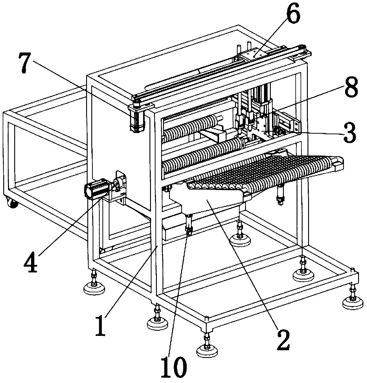
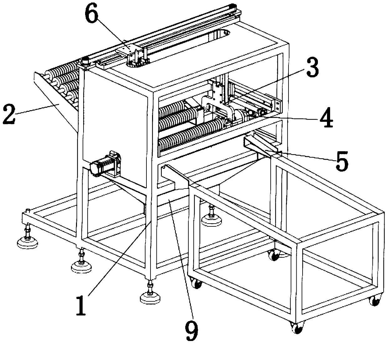
[0040] A roller glue spraying device, comprising: a frame 1, a discharge seat 2, a transfer assembly 3, a rotary drive assembly 4, a glue spray assembly and a material receiving seat 5, the rotary drive assembly 4 is installed on the frame 1, and the discharge seat 2 and the material receiving seat 5 are arranged on both sides of the rotary drive assembly 4, the transfer assembly 3 is slidably installed between the material discharging seat 2 and the material receiving seat 5, the glue spraying assembly is slidably installed on the frame 1, and the glue spraying assembly is located on Rotate the top of the drive assembly 4.

[0041] In this way, use a round tube to pass through the through hole in the middle of the rollers, the rollers are arranged along the round tube, each string of rollers is arranged on the discharge seat 2 in turn, and the transfer component 3 transfers the round tube with the rollers to the rotary drive component 4 Next, the rotating drive assembly 4 dri...

Embodiment 2

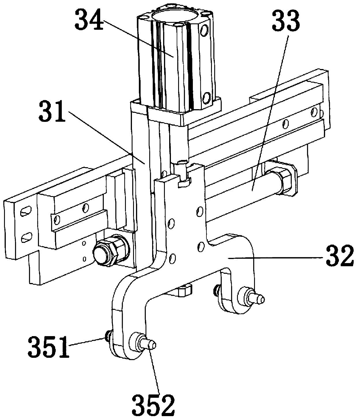
[0049] In this embodiment, two groups of transfer assemblies 3 are arranged at intervals, and the transfer assembly 3 includes a second slide seat 31, a second lifting seat 32, a second drive assembly 33, a second linear motion power device 34 and a telescopic rod assembly 35, The second sliding seat 31 is slidably installed on the frame 1, and the second driving assembly 33 is installed on the frame 1. The second driving assembly 33 is connected with the second sliding seat 31 to drive the second sliding seat 31 to slide, and the second lifting The seat 32 is slidably installed on the second sliding seat 31, the second linear motion power device 34 is fixed on the second sliding seat 31, the output shaft of the second linear motion power device 34 is connected with the second lifting seat 32, and the telescopic rod assembly 35 Installed on the second lifting seat 32. Specifically, the second linear motion power device 34 is an air cylinder. Specifically, the distance between...


PUM


Abstract

The invention relates to a glue spraying device for rollers. The device comprises a rack, a material placing seat, a transferring assembly, a rotary driving assembly, a glue spraying assembly and a receiving seat, wherein the rotary driving assembly is installed on the rack, the material placing seat and the receiving seat are arranged on the two sides of the rotary driving assembly, the transferring assembly is installed between the material placing seat and the receiving seat in a sliding mode, the glue spraying assembly is installed on the rack in a sliding mode, and the glue spraying assembly is located above the rotary driving assembly. By the adoption of the scheme, glue can be conveniently sprayed to the rollers, and production efficiency is high.

Description

technical field [0001] The invention relates to a roller glue spraying device. Background technique [0002] In the elevator door equipment, a roller assembly is usually provided, and the roller assembly is installed at the bottom of the elevator door to facilitate the sliding of the elevator door. The roller assembly usually consists of a roller, a rotating shaft and a bearing. The bearing fits in the roller, and the rotating shaft fits in the bearing. An annular groove is arranged outside the roller, and polyurethane is filled in the annular groove. In the production process of the roller, it is necessary to spray glue on the surface of the roller first, and then fill it with polyurethane. In order to facilitate spraying glue on the surface of the roller, it is necessary to string a large number of rollers outside the round pipe first, and then use a glue spraying tool to spray glue on the roller. Compared with spraying glue on a single roller, the efficiency of this glu...

Claims


Application Information

Patent Timeline
IPC IPC(8): B05B13/02B05B13/04
CPCB05B13/0228B05B13/025B05B13/041
Inventor 李俊凯张进东
Owner 浙江智菱科技有限公司
Why Eureka
Try Eureka