
Tunnel damage detection management system based on mobile train vibration signal

A technology of vibration signal and management system, applied in signal transmission system, railway signal and safety, processing response signal of detection, etc., can solve the problem of failure to detect tunnel structure operation accident in time, full coverage monitoring of difficult tunnel, no detection method, etc. problems, to achieve the effect of reducing monitoring and maintenance costs, ensuring the safety of people's property, and reducing costs and risks

Active Publication Date: 2020-06-09
TONGJI UNIV
View PDF23 Cites 8 Cited by
  • Summary
  • Abstract
  • Description
  • Claims
  • Application Information

AI Technical Summary

Problems solved by technology

At present, tunnel damage detection methods mainly rely on deformation monitoring and vibration monitoring. Due to cost constraints, fixed sensors can only be deployed in sensitive areas for monitoring; in other areas, maintenance personnel can only rely on on-site inspections or machine vision identification after trains are out of service. And basically only the apparent damage can be identified, there is no more efficient detection method for the damage inside the tunnel lining and behind the wall
At the same time, limited by the limitations of sensor technology, the health monitoring of tunnel structures is more in the form of "points instead of surfaces", which makes it difficult to monitor the full coverage of regional tunnels in the subway network, and cannot detect tunnel structural damage in time, resulting in unnecessary operation ACCIDENT

Method used


Image

  • Tunnel damage detection management system based on mobile train vibration signal
  • Tunnel damage detection management system based on mobile train vibration signal
  • Tunnel damage detection management system based on mobile train vibration signal

Examples


Embodiment 1

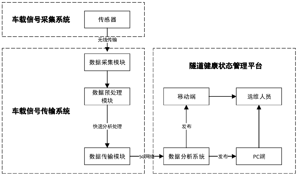
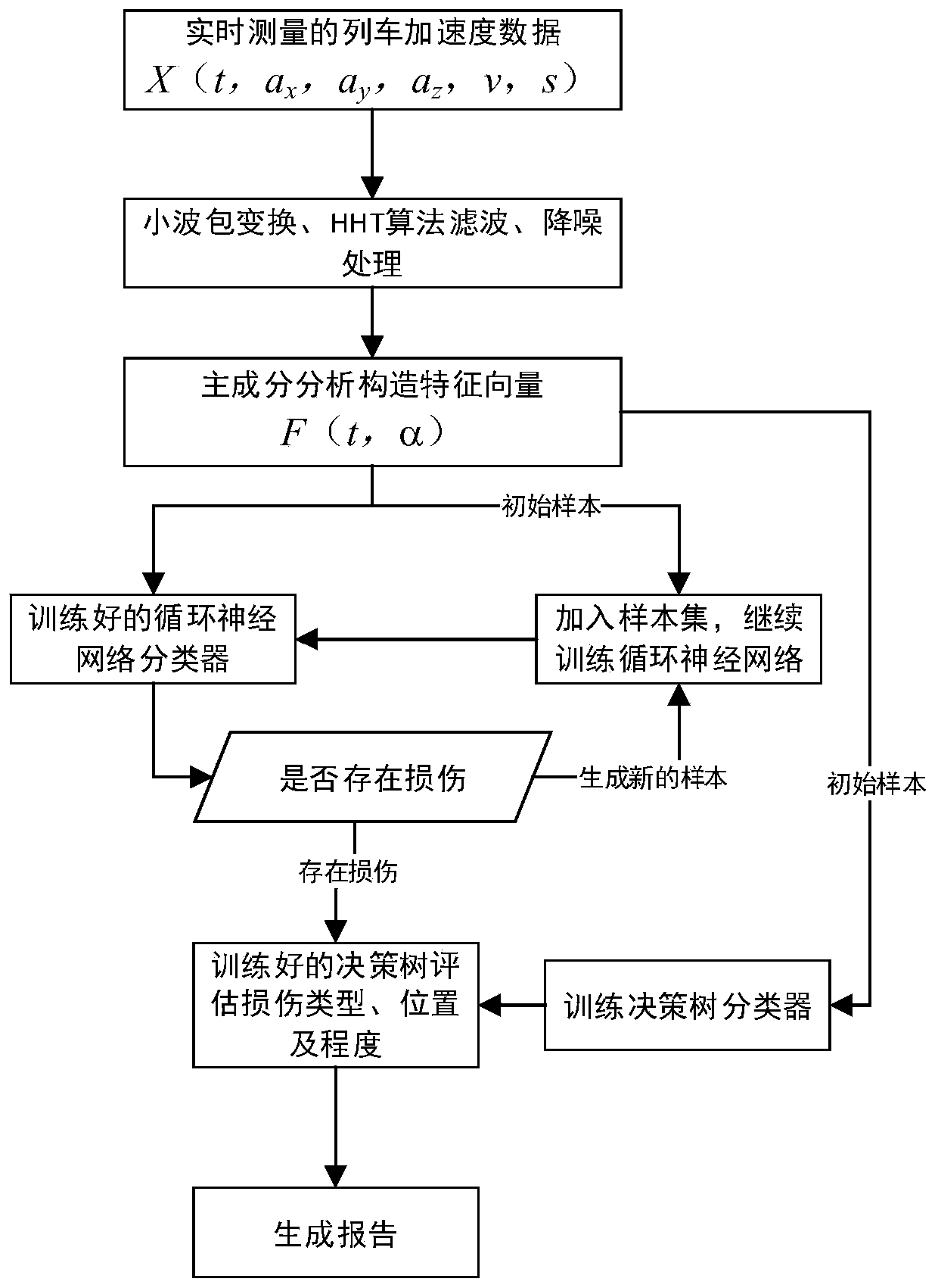
[0029] like figure 1 As mentioned above, the present invention provides a tunnel damage detection and management method based on the vibration signal of a moving train. The main process of the method is as follows: figure 2 Shown: Use sensors to collect vibration signals of trains in service, obtain train vibration data, transmit them to the on-board signal transmission system via radio, perform preprocessing and compression, and then transmit them to the cloud server through the 5G network. After processing and analyzing the data, the tunnel and its The damage of ancillary structures can be determined, and the approximate location of the damage can be determined and published on the management cloud platform to provide a reference for real-time understanding of the tunnel health status, which greatly improves the tunnel detection efficiency and reduces its cost and operational risk.

[0030] Depend on figure 1 As shown, the shield tunnel damage detection and management me...


PUM


Abstract

The invention provides a tunnel damage detection management system based on a mobile train vibration signal. Defects or damage of a subway tunnel structure and a soil layer behind the wall are recognized by collecting, transmitting and analyzing a vehicle-mounted acceleration signal. The system according to the method comprises a serving train or a detection vehicle which runs in a subway tunnel;a signal acquisition sensor which is arranged on the mobile train and is used for acquiring signals such as vibration transmitted to the train by a train tunnel soil body coupling system; a signal collection and transmission module which is installed in the train and preprocesses and compresses the signals and transmits the signals to an analysis center through a network; a data processing and analyzing server which is used for performing data analysis by utilizing professional data processing software and AI, quickly identifying the damage of the tunnel and the accessory structure thereof andjudging the position and the type of the tunnel; and a tunnel management platform which is used for publishing tunnel real-time detection information and a health state, giving a damage alarm and pushing the damage alarm to related personnel to take measures. The tunnel damage detection method is efficient, economical and high in accuracy.

Description

technical field [0001] The invention belongs to the field of civil engineering and the field of computer technology, and relates to a shield tunnel damage detection method, in particular to a tunnel damage detection management method based on a vibration signal of a moving train. Background technique [0002] At present, with the rapid development of the city and the construction of a large number of tunnels, the subway has become the main lifeline of urban transportation. However, tunnel safety has also become an increasingly important issue. At present, the method of tunnel damage detection mainly relies on deformation monitoring and vibration monitoring. Due to cost constraints, fixed sensors can only be deployed in sensitive areas for monitoring; other areas can only rely on maintenance personnel to conduct on-site inspections or machine vision recognition after the train is stopped. And basically only the apparent damage can be identified, and there is no more efficien...

Claims


Application Information

Patent Timeline
Patent Type & Authority Applications(China)
IPC IPC(8): G01N29/04G08C17/02E21F17/00
CPCG01N29/045G08C17/02E21F17/00G01N29/4481G01N29/4472G01N2291/0234H04Q9/00H04Q2209/823H04Q2209/86G01N29/14G01N29/449G01N2291/0232G01N29/46E21F17/18G01N29/265B61L25/021B61L25/025G01N29/043G01N2291/2636G06N3/02H04Q2209/40
Inventor 谢雄耀张永来李鸿桥周彪
Owner TONGJI UNIV
Learn More