Automatic online testing system for millimeter wave packaging antenna

An online test, millimeter wave technology, applied in the antenna radiation pattern and other directions, can solve the problems of high cost, difficult large-scale application, large volume, etc., to save cost and space, test vector magnitude error and throughput, and small volume Effect

Inactive Publication Date: 2020-06-09
苏州度风科技有限公司
View PDF6 Cites 6 Cited by
  • Summary
  • Abstract
  • Description
  • Claims
  • Application Information

AI Technical Summary

Problems solved by technology

[0011] The purpose of the present invention is to overcome the technical problems of large volume, high cost, and difficulty in large-scale application of the above-mentioned prior art, and provide an automated online test system for millimeter-wave packaged antennas

Method used


Image

  • Automatic online testing system for millimeter wave packaging antenna
  • Automatic online testing system for millimeter wave packaging antenna
  • Automatic online testing system for millimeter wave packaging antenna

Examples


Embodiment 1

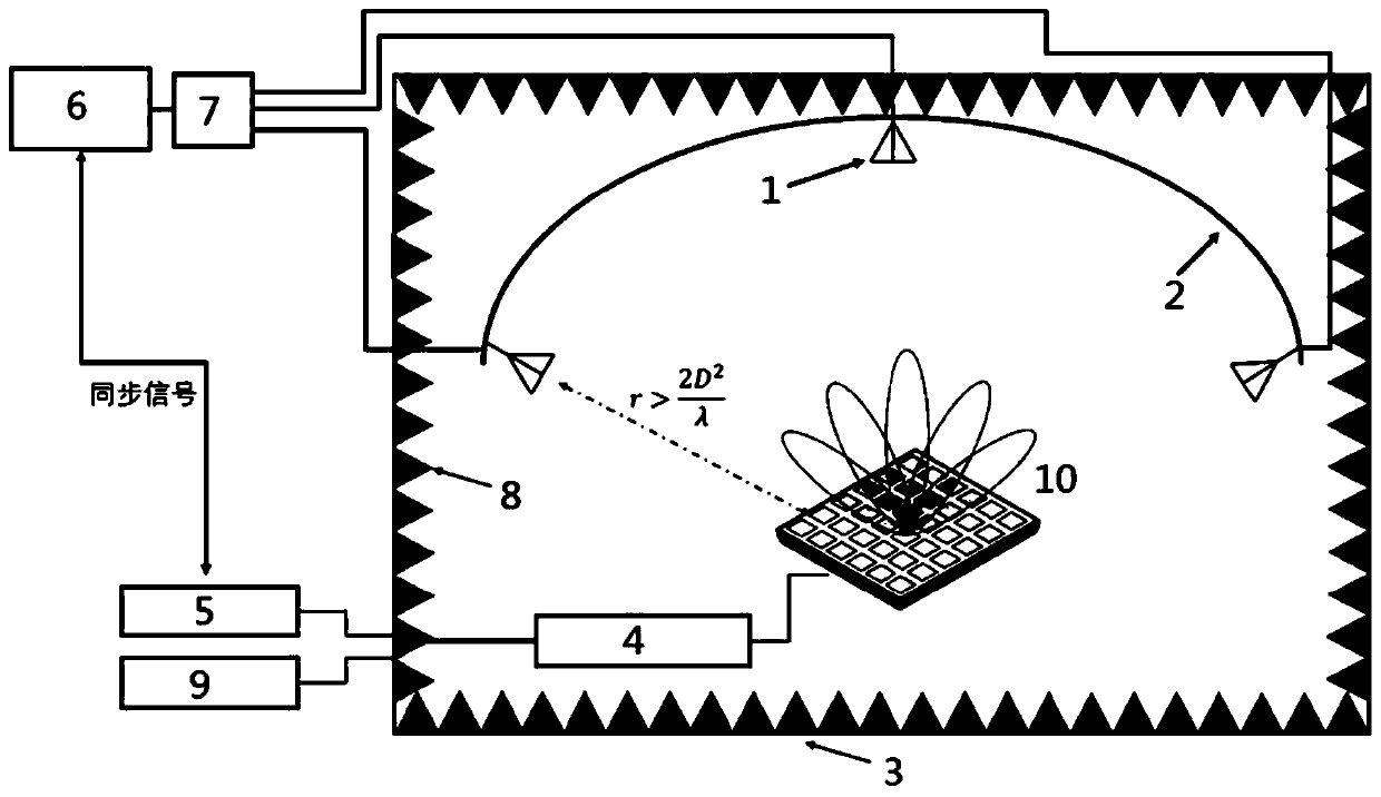
[0043] Such as figure 1 As shown, this embodiment provides a millimeter-wave packaged antenna automated online testing system that can be used on a large scale on the production line, including a small shielding box 3, a radio frequency transceiver module, a transceiver antenna probe 1, a probe bracket 2, and an antenna interface to be tested The board 4 and the upper computer, the transceiver antenna probe 1, the probe bracket 2 and the antenna interface board 4 to be tested are arranged in a small shielding box 3 to shield external interference, and the radio frequency transceiver module is respectively connected to the transceiver antenna probe 1 and the antenna interface board 4 to be tested And the upper computer, the transceiver antenna probe 1 is installed on the probe bracket 2; the radio frequency transceiver module includes a radio frequency transmission circuit 6 and a receiver 5, when testing, the antenna to be tested 10 is installed on the antenna interface board t...

Embodiment 2

[0054] Such as Image 6 As shown, in the millimeter wave packaged antenna automatic online testing system provided in this embodiment, the radio frequency transceiver module is replaced by the assembly 10 of a base station simulator, a spectrum analyzer and a frequency conversion module. Test the error vector magnitude, adjacent channel leakage ratio and throughput through the base station simulator, spectrum analyzer and frequency conversion module. In this extended configuration, although the test speed will be slower, the complete performance of the antenna-in-package can be completely tested.

[0055] The main working steps of the millimeter wave packaged antenna automated online testing system of this embodiment include:

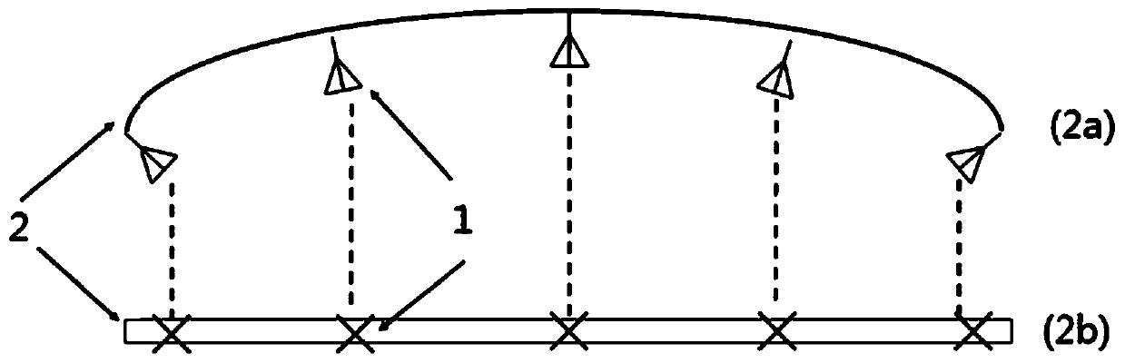
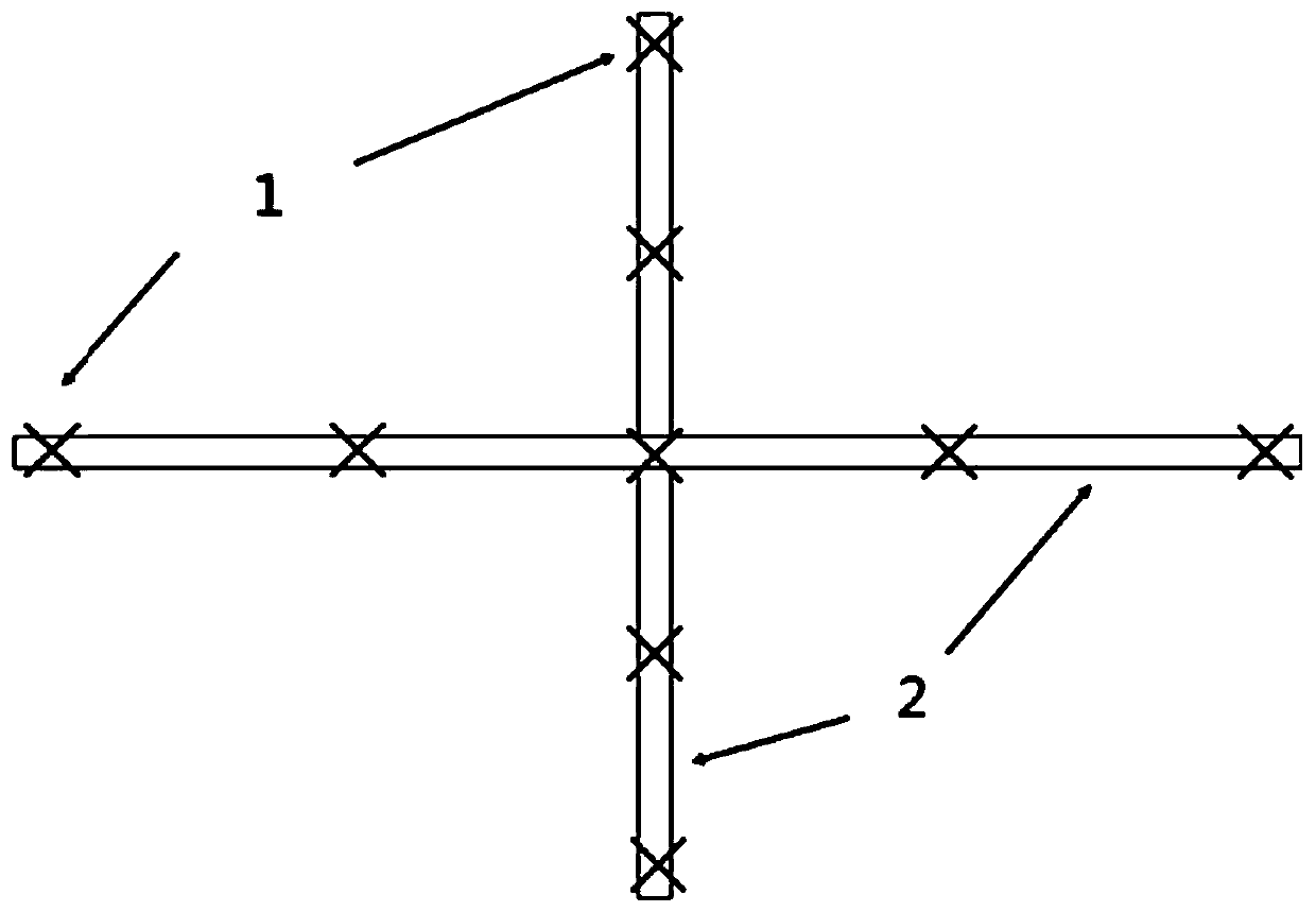
[0056] 1. According to the test requirements of the packaged antenna, configure a one-dimensional or two-dimensional probe bracket, and install the transceiver antenna probe at the corresponding test angle.

[0057] 2. Use the base station simulator +...


PUM


Abstract

The invention relates to an automatic online testing system for a millimeter wave packaging antenna. The automatic online testing system comprises a small shielding box, a radio frequency transceivingmodule, a transceiving antenna probe, a probe support, a to-be-tested antenna interface board and an upper computer, wherein the transceiving antenna probe, the probe support and the to-be-tested antenna interface board are arranged in the small shielding box, the radio frequency transceiving module is connected with the transceiving antenna probe, the o-be-tested antenna interface board and theupper computer, and the transceiving antenna probe is installed on the probe support. A to-be-tested antenna is installed on the to-be-tested antenna interface board during testing. The transceiving antenna probe and the to-be-tested antenna radiate a specific frequency signal generated by the radio frequency transceiving module to a free space in the small shielding box at the same time and receive a feedback signal, and the upper computer collects antenna information of the transceiving antenna probe and the to-be-tested antenna so as to test the performance of the to-be-tested antenna. Compared with the systems in the prior art, the system has the advantages that the test result can be obtained quickly, the cost and the space are saved, and the system can be used on a production line ona large scale.

Description

technical field [0001] The invention belongs to the field of automatic testing equipment, and relates to a millimeter-wave packaged antenna test scheme, in particular to an automatic online test system for a millimeter-wave packaged antenna. Background technique [0002] With the development of 5G communication technology, the millimeter wave frequency band is put into use. Due to its small size and high integration level, the antenna-in-package has become the preferred solution in the application scenarios of terminals and micro base stations. Companies such as Qualcomm, Intel, and Google have developed packaged antennas for 28GHz, 60GHz, and 94GHz frequency bands, and they are ready to be put into use. [0003] Due to the high integration of the antenna and the radio frequency part of the existing packaged antenna, the interface used for the traditional conduction test has basically been cancelled, and most of the performance tests will be tested through the over-the-air ...

Claims


Application Information

Patent Timeline
Patent Type & Authority Applications(China)
IPC IPC(8): G01R29/10
CPCG01R29/10
Inventor 张睿恒杨广立
Owner 苏州度风科技有限公司
Why Eureka
Try Eureka