
Display panel and display device

A technology for display panels and display areas, which is applied to identification devices, instruments, etc., and can solve problems such as poor bending resistance, affecting the performance of display panels, and fractures.

Inactive Publication Date: 2020-06-09
EVERDISPLAY OPTRONICS (SHANGHAI) CO LTD
View PDF5 Cites 1 Cited by
  • Summary
  • Abstract
  • Description
  • Claims
  • Application Information

AI Technical Summary

Problems solved by technology

However, the existing outer pin area structure has poor bending resistance, and the metal traces in the outer pin area are prone to breakage when bent together with the substrate, which affects the performance of the display panel.

Method used


Image

  • Display panel and display device
  • Display panel and display device
  • Display panel and display device

Examples


Embodiment Construction

[0025] The present invention will be further described in detail below in conjunction with the accompanying drawings and embodiments. It should be understood that the specific embodiments described here are only used to explain the present invention, but not to limit the present invention. In addition, it should be noted that, for the convenience of description, only some structures related to the present invention are shown in the drawings but not all structures.

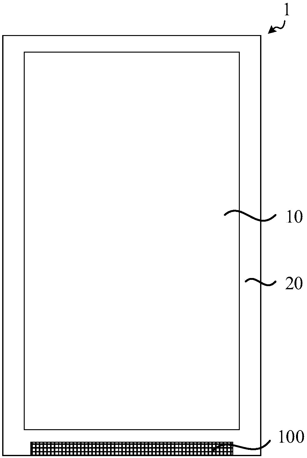
[0026] figure 1 It is a schematic structural diagram of a display panel provided by an embodiment of the present invention. figure 2 It is a schematic structural diagram of an outer lead area provided by an embodiment of the present invention. see figure 1 and figure 2 , an embodiment of the present invention provides a display panel 1, comprising: a display area 10 and a frame area 20; the frame area 20 includes an Outer Lead Bonding (OLB) 100, and the outer lead area 100 includes substrates stacked in seque...


PUM

PropertyMeasurementUnit
widthaaaaaaaaaa
thicknessaaaaaaaaaa
depthaaaaaaaaaa

Abstract

The embodiment of the invention discloses a display panel and a display device. The display panel comprises a display area and a frame area. The frame area comprises an outer pin area, and the outer pin area comprises a substrate, a metal wire layer and a first thin film layer which are stacked in sequence; the first film layer covers the metal wire layer; and at least one groove is formed in oneside, far away from the metal wire layer, of the first thin film layer. According to the technical scheme provided by the embodiment of the invention, the first thin film layer is arranged on the metal wire layer in the outer pin area, and at least one groove is formed in the first thin film layer, so that residual stress in the bending process is reduced, the situation that each film layer cracksor fractures when the outer pin area is bent can be avoided, and the bending resistance of the whole outer pin area is improved.

Description

technical field [0001] Embodiments of the present invention relate to display technologies, and in particular, to a display panel and a display device. Background technique [0002] With the development of science and technology, the requirements for the display panel are gradually increasing. In order to have a larger display area, the display panel is gradually developing towards a higher screen-to-body ratio. [0003] In order to achieve a display panel with a high screen-to-body ratio, the frame area of ​​the display panel will be reduced as much as possible to achieve a narrow frame or even no frame. In order to achieve a high screen-to-body ratio and a variety of shapes displayed on the display panel, it is necessary to bend the outer lead area to reduce the non-display area. However, the existing outer lead area structure has poor bending resistance, and the metal traces in the outer lead area are prone to breakage when bent together with the substrate, which affects...

Claims


Application Information

Patent Timeline
Patent Type & Authority Applications(China)
IPC IPC(8): G09F9/30
CPCG09F9/30
Inventor 苑志磊黄成沛高胜王忠春
Owner EVERDISPLAY OPTRONICS (SHANGHAI) CO LTD
Learn More