
Rotary tower crane

A technology of tower cranes and jibs, which is applied to cranes and other directions, and can solve problems such as inconvenient high component weight and size

Active Publication Date: 2020-06-12
LIEBHERR WERK BIBERACH
View PDF7 Cites 0 Cited by
  • Summary
  • Abstract
  • Description
  • Claims
  • Application Information

AI Technical Summary

Problems solved by technology

[0008] A general disadvantage of topless rotating tower cranes is the high component weight and size of the boom assembly which is not easily transportable due to the high boom bending moment, especially, with large size cranes >300mt

Method used


Image

  • Rotary tower crane
  • Rotary tower crane

Examples


Embodiment Construction

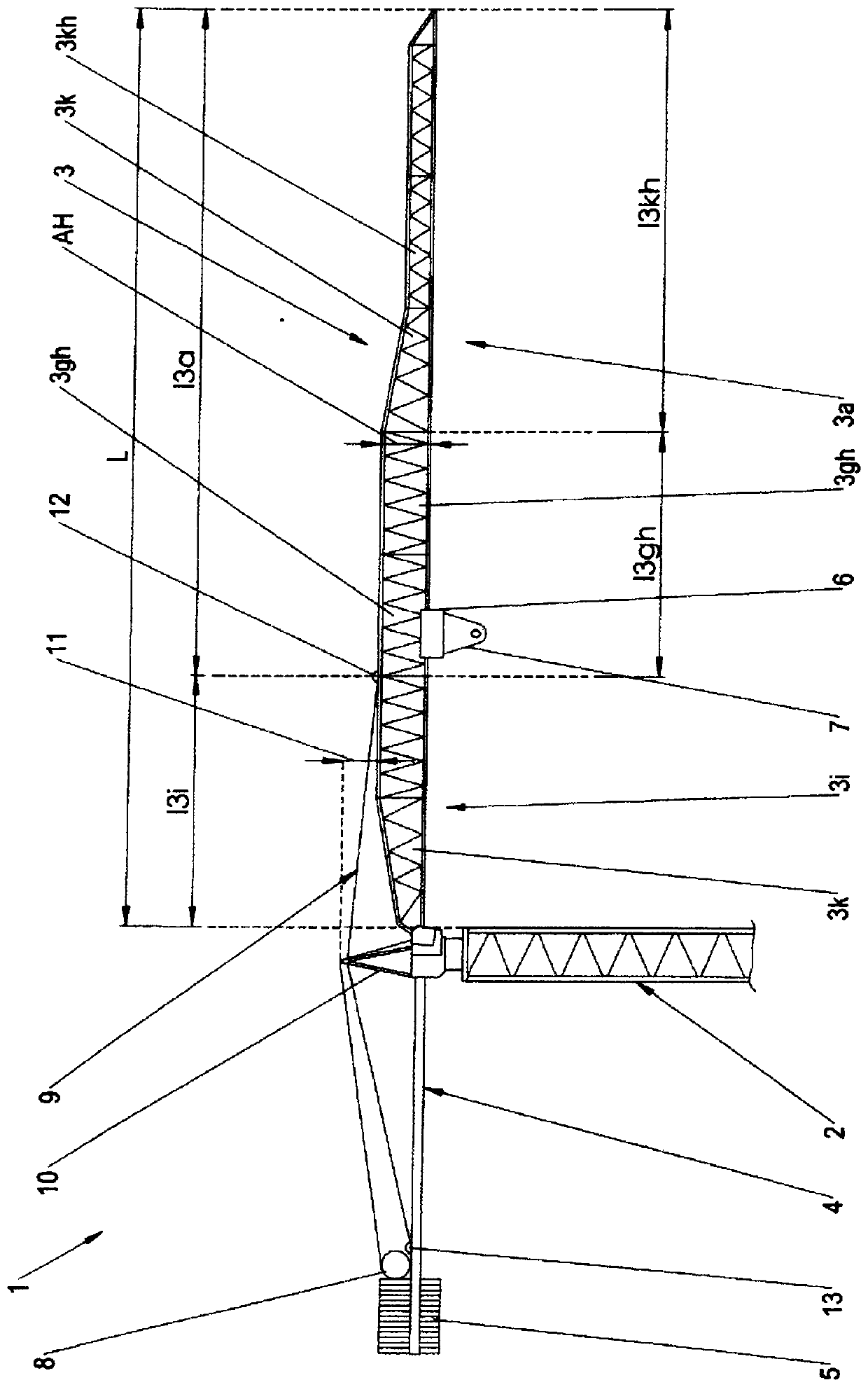
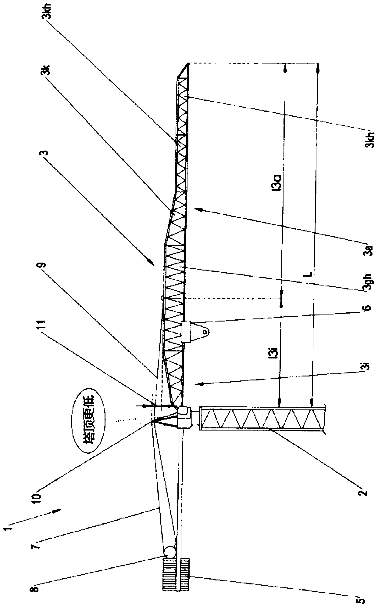
[0034] Such as figure 1 It is shown that the rotating tower crane 1 comprises a vertical tower 2 which may be formed as a mast and may for example have a rectangular cross-section.

[0035] A jib 3 , aligned generally in a flat manner (in particular, approximately horizontal), is articulated to the upper end of the tower 2 . A counterweight 5 , which can likewise be arranged in a flat manner (in particular horizontally) and which can support a counterweight 5 , can be provided at the side of the tower 2 opposite the jib 3 .

[0036] The trolley 6 may be arranged longitudinally advanceable at the jib 3 in a manner known per se to be able to lower and raise the hoisting wire 7 and the hoisting hook connected to it closer to the tower 2 or further away Tower 2. The hoisting wire rope 7 can advantageously be lowered and raised by means of a hoisting device 8 which can be arranged at the counterweight 4 near the counterweight 5 , in particular, immediately before the counterweigh...


PUM


Abstract

The invention relates to a rotary tower crane with a tower (2), which carries a jib (3) and a counterjib (4), with a jib stay (9) being guided from a tower top (10) to the jib and to the counterjib. According to the invention the jib stay tensions only an inner jib portion, the length of which is less than 40% of the total length of the jib, and an outer portion, the length of which is more than 60% of the total length of the jib, forms an untensioned bending beam jib which comprises at least one jib piece which tapers in height and which is adjoined on the inner side by at least one jib partof greater height and on the outer side by a jib piece of smaller height.

Description

technical field [0001] The invention relates to a rotating tower crane having a tower supporting a jib and a counter jib, wherein jib guys are guided from the top of the tower to the jib and to the counter jib. Background technique [0002] It is known to hold the jib with guy wires to be able to take up large loads in the case of rotating tower cranes with relatively large radii (i.e. large jib lengths), of which usually one, two or also three Stay ropes or stays are guided from the tower top protruding above the jib to the jib and are fastened there. Depending on the jib length, the point of attachment of the stay rope or stay string at the jib can be approximately central, or can be arranged in the inner third and / or in the outer third. "Inner" here means the jib section positioned closer to the tower, and "outer" means the jib section protruding further and spaced further from the tower. For example, a first brace may be fastened approximately one-third of the total bo...

Claims


Application Information

Patent Timeline
IPC IPC(8): B66C23/26B66C23/72B66C23/82
CPCB66C23/26B66C23/72B66C23/82B66C23/64
Inventor 托马斯·赫西
Owner LIEBHERR WERK BIBERACH
Learn More