
A Capacitor Voltage Balance Control Method for Modular Multilevel Matrix Converter

A modular multi-level, matrix converter technology, applied in the direction of converting AC power input to AC power output, electrical components, output power conversion devices, etc., can solve problems such as inability to ensure circulating current

Active Publication Date: 2021-04-06
NANJING NORMAL UNIVERSITY
View PDF4 Cites 0 Cited by
  • Summary
  • Abstract
  • Description
  • Claims
  • Application Information

AI Technical Summary

Problems solved by technology

[0004] The Chinese Patent Publication No. CN106786535A "Grid Simulation Device and Its Control Method" proposes a circulating current control method for M3C capacitor voltage balance. In this method, no constraints are imposed on the circulating current, and it cannot be ensured that the circulating current will not affect the input and output currents; Chinese patent CN107240922A compares the given value of the DC voltage of the nine bridge arms of M3C with the average value to obtain a balanced bridge arm There are 9 active currents of power, but the sum of these 9 active currents obtained through proportional integral control is not necessarily 0, and may flow into the input and output currents; "Hierarchical" published in "IEEE Transactions on Power Electronics" "Energy Balance Control Method for M3C based on InjectingOutput Frequency Circulating Currents" (author Ma Jiankai, etc.) proposes a control method for single-frequency circulating current injection. By injecting circulating current of output frequency, the power grid is unbalanced. Capacitor voltage balance control, but when the transmission power of the bridge arm is unbalanced, the injected circulating current of the output frequency will flow into the input side power grid

Method used


Image

  • A Capacitor Voltage Balance Control Method for Modular Multilevel Matrix Converter
  • A Capacitor Voltage Balance Control Method for Modular Multilevel Matrix Converter
  • A Capacitor Voltage Balance Control Method for Modular Multilevel Matrix Converter

Examples


Embodiment Construction

[0051] Below in conjunction with accompanying drawing and specific embodiment, further illustrate the present invention, should be understood that these embodiments are only for illustrating the present invention and are not intended to limit the scope of the present invention, after having read the present invention, those skilled in the art will understand various aspects of the present invention Modifications in equivalent forms all fall within the scope defined by the appended claims of this application.

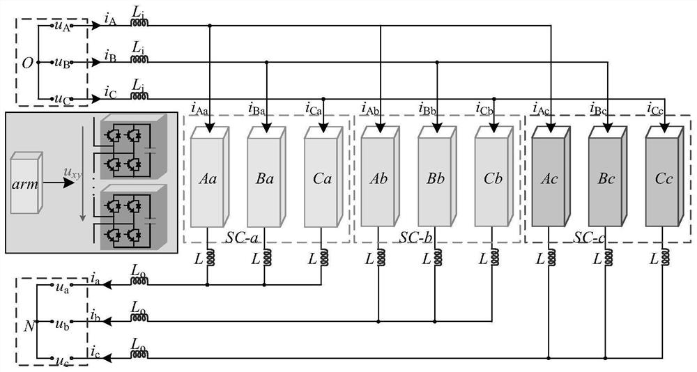
[0052] The invention is mainly used for M3C capacitor voltage balance control, and is widely used in the fields of frequency conversion speed regulation, high-voltage and low-frequency grid connection of offshore wind power, power electronic transformers and the like. figure 1 The topological structure of M3C is shown, in which the input side of M3C is connected to a 50 / 3Hz offshore low-frequency wind power plant, and the voltage and current are respectively represented b...


PUM


Abstract

The invention discloses a capacitor voltage balance control method of a modularized multilevel matrix converter. This method first obtains the reference value of the input and output current components in the bridge arm current through output power control and total capacitor voltage balance control; then, through the bridge arm capacitor voltage balance control based on dual-frequency circulating current injection, the bridge arm current is obtained The reference value of the two frequency circulating current components in the middle, and then find the reference value of the bridge arm current; finally, compare the bridge arm current actually measured by the current sensor with the reference value of the bridge arm current, through proportional integral control, and then use the input and output voltage Feed-forward control of the bridge arm voltage reference value is obtained, and used to obtain the signal for controlling the switch of the sub-module. The present invention does not need to perform complex transformation on the circuit, and when the transmission power of the bridge arm is unbalanced, it can not only realize the balance of the capacitor voltage, but also ensure that the injected circulating current will not affect the input and output currents.

Description

technical field [0001] The invention belongs to the technical field of application of high-voltage and high-power power electronic technology in power systems, and in particular relates to a method for controlling capacitor voltage balance of a modular multilevel matrix converter (Modular Multilevel Matrix Converter, M3C). Background technique [0002] Modular multilevel matrix converter combines the characteristics of traditional matrix converter and multilevel converter. It is an AC / AC converter that can realize direct frequency conversion. In addition, it also has the ability of bidirectional flow of energy, and can realize any power factor on the input side, and any step-up and step-down ratio on the output side, so it has broad application prospects in the fields of frequency conversion speed regulation and low-frequency high-voltage AC power transmission. [0003] For M3C, power transfer needs to be carried out through the bridge arm between the input and output, which...

Claims


Application Information

Patent Timeline
Patent Type & Authority Patents(China)
IPC IPC(8): H02M5/293
CPCH02M5/293
Inventor 孙毅超鄢寅宇张金龙曹泽宇
Owner NANJING NORMAL UNIVERSITY
Learn More