Hybrid MMC control method and system

A hybrid, pulse-controlled technology, applied in the direction of single-network parallel feeding arrangement, power transmission AC network, etc., can solve the problem of lack of control method system and other problems

Pending Publication Date: 2020-12-29
CHINA EPRI ELECTRIC POWER ENG CO LTD +3
View PDF0 Cites 0 Cited by
  • Summary
  • Abstract
  • Description
  • Claims
  • Application Information

AI Technical Summary

Problems solved by technology

[0004] In order to solve the problem existing in the prior art that the hybrid MMC lacks an effective control method system under the step-down/half-voltage operation of the conver...

Method used


Image

  • Hybrid MMC control method and system
  • Hybrid MMC control method and system
  • Hybrid MMC control method and system

Examples


Embodiment 1

[0069] This embodiment provides a hybrid MMC control method, including:

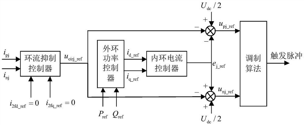
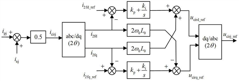
[0070] The traditional MMC overall control block diagram is as follows: figure 2 shown. P ref , Q ref is the command value of active and reactive power input to the outer loop power controller, i d_ref i q_ref It is the dq axis current reference value output by the outer loop power controller. Adding additional control signal u for circulation suppression cirj_ref After that, the control system finally outputs the upper and lower bridge arm voltage reference signal u pj_ref and u nj_ref , which is the voltage reference value of the converter, and then the corresponding trigger pulse is generated through the multi-level carrier phase-shift modulation algorithm, and then the opening and closing of each sub-module is controlled.

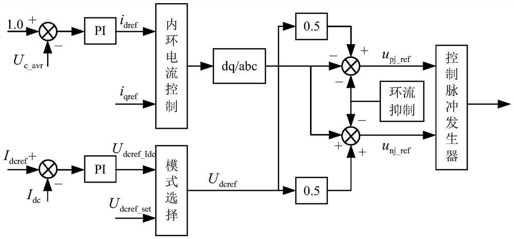
[0071] When the step-down / half-voltage operation of the converter station, single-valve group online switching on and off, and DC fault ride-through conditions, the contr...

Embodiment 2

[0092] This embodiment provides a hybrid MMC control method system, including:

[0093] Inverter, circulation suppression controller, mode selection controller and control pulse generator;

[0094] The converter is used to formulate a voltage reference value of the converter;

[0095] The circulating current suppression controller is used to formulate the circulating current suppression voltage value under normal working conditions, step-down / half-voltage operation of the converter station, online switching of single valve group, and DC fault ride-through working conditions;

[0096] The mode selection controller is used to formulate the DC voltage given value under normal working conditions and converter station step-down / half-voltage operation, single-valve group on-line switching and DC fault ride-through working conditions;

[0097] The pulse control occurs, and is used to formulate control pulses under normal working conditions, step-down / half-voltage operation of conver...


PUM


Abstract

The invention discloses a hybrid MMC control method and system. The method comprises steps of carrying out the step-down/half-voltage operation of a converter station, carrying out the online switching of a single valve group, and setting a converter voltage reference value according to the capacitor voltage of a sub-module in an MMC converter valve under a DC fault ride-through condition; and formulating a control pulse according to the circulation injection voltage value formulated by the bridge arm circulation and the direct current voltage given value formulated by the direct current givenvalue, and controlling the input of the hybrid MMC. According to the method, the current zero crossing point of the MMC bridge arm can be ensured according to the converter voltage reference value set by the capacitor voltage of the sub-module in the MMC converter valve under special working conditions, the capacitor voltage balance is realized, and system crash caused by continuous charging of the capacitor voltage when the current of the bridge arm is not at the zero crossing point and separation of the capacitor voltage from the capacitor voltage of the full-bridge sub-module is avoided; the loop current injection voltage value is set according to the loop current of the MMC converter valve bridge arm, the bridge arm current always has a zero crossing point through the loop current injection link, and safe operation of the MMC bridge arm is ensured.

Description

technical field [0001] The invention relates to the technical field of flexible direct current transmission, in particular to a hybrid MMC control method and system. Background technique [0002] Faced with the severe challenges of global energy security, environmental pollution and climate change, the country is vigorously developing and utilizing renewable clean energy and optimizing the energy structure. The grid commutated converter (LCC) is mature and reliable, and it is an efficient long-distance large-capacity power transmission method, but there is a high risk of commutation failure in weak AC systems. The flexible DC converter (VSC) has the advantages of independent active and reactive power adjustment, weak grid connection, no risk of commutation failure, and no need for synchronous networking. technical means. DC transmission is developing in the direction of higher voltage, larger transmission capacity and longer distance transmission. VSC-LCC hybrid multi-term...

Claims


Application Information

Patent Timeline
IPC IPC(8): H02J3/36H02J3/38
CPCH02J3/36H02J3/38Y02E60/60
Inventor 栾洪洲查鲲鹏张帆高瑞雪黄金魁白雪朱晓超
Owner CHINA EPRI ELECTRIC POWER ENG CO LTD
Why Eureka
Try Eureka