Vibration damper for a tubular drive shaft

a technology of vibration damper and drive shaft, which is applied in the direction of shock absorber, mechanical apparatus, inertia effect damper, etc., can solve the problems of disassembly of the propeller shaft, and achieve the effect of effectively damping the flexural vibration increasing the imbalance of the propeller shaft, and requiring little effor

Inactive Publication Date: 2005-01-04
DAIMLER AG
View PDF31 Cites 55 Cited by
  • Summary
  • Abstract
  • Description
  • Claims
  • Application Information

AI Technical Summary

Benefits of technology

An underlying object of the present invention is therefore that of creating a vibration damper that effectively damps the flexural vibrations of the propeller shaft for specific frequencies without perceptibly increasing the imbalance of the propeller shaft—and thus also the noise emission—in other frequency ranges. As a result of its design, the vibration damper is installable at any desired point with little effort. The installation of multiple vibration dampers can also be possible. In addition, safe vehicle operation is to be guaranteed even in the event of detachment or breakage of the rubber spring elements retaining the mass body.

Problems solved by technology

Without the stop elements, the imbalance additionally generated by the mass body could, in this situation, destroy the propeller shaft.

Method used


Image

  • Vibration damper for a tubular drive shaft
  • Vibration damper for a tubular drive shaft
  • Vibration damper for a tubular drive shaft

Examples


Embodiment Construction

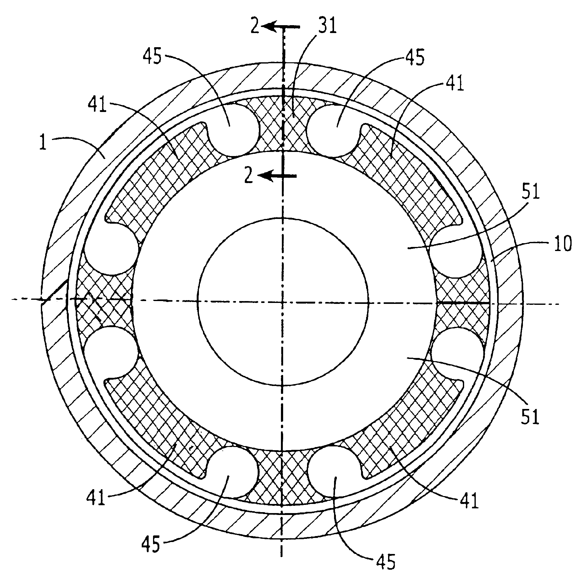
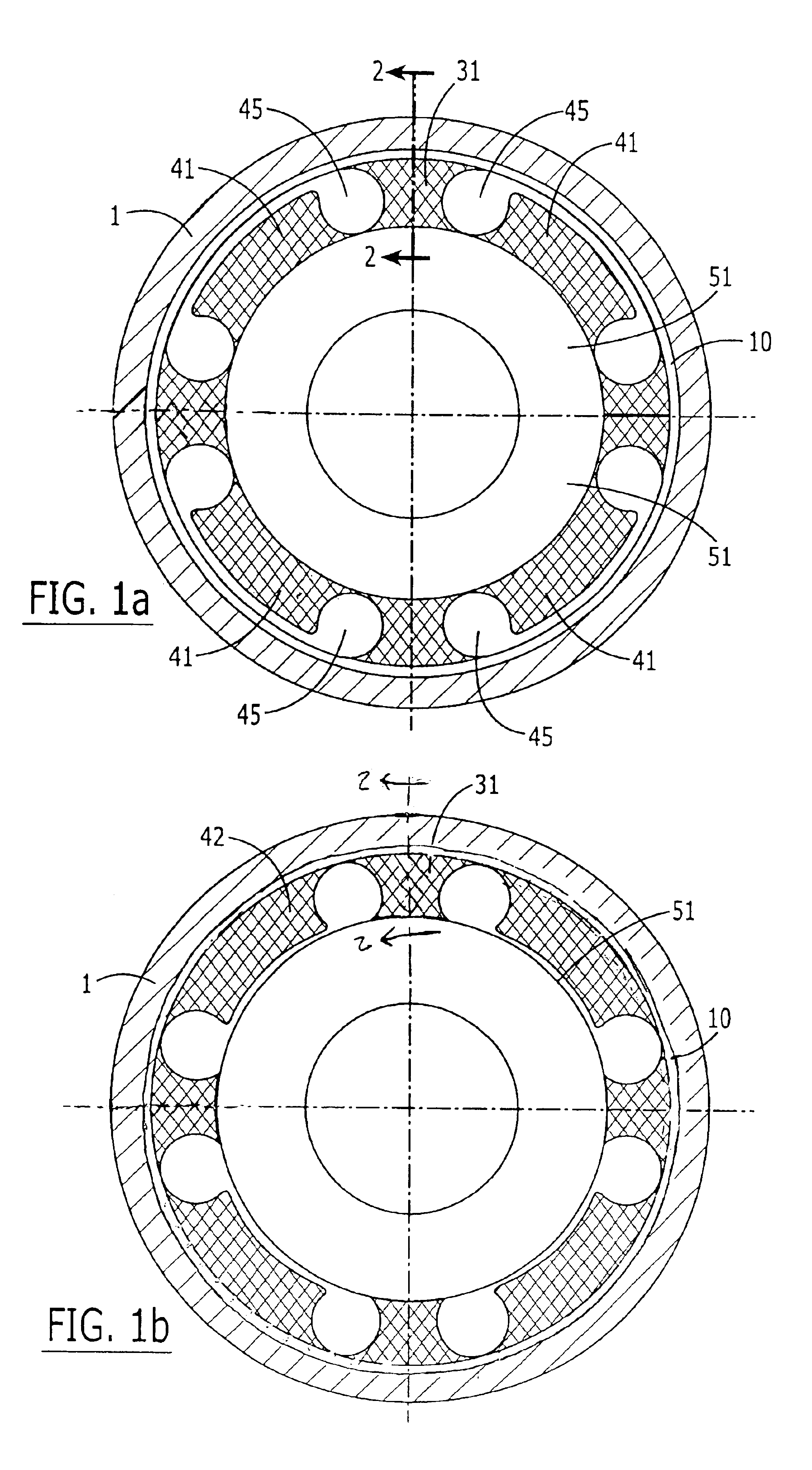
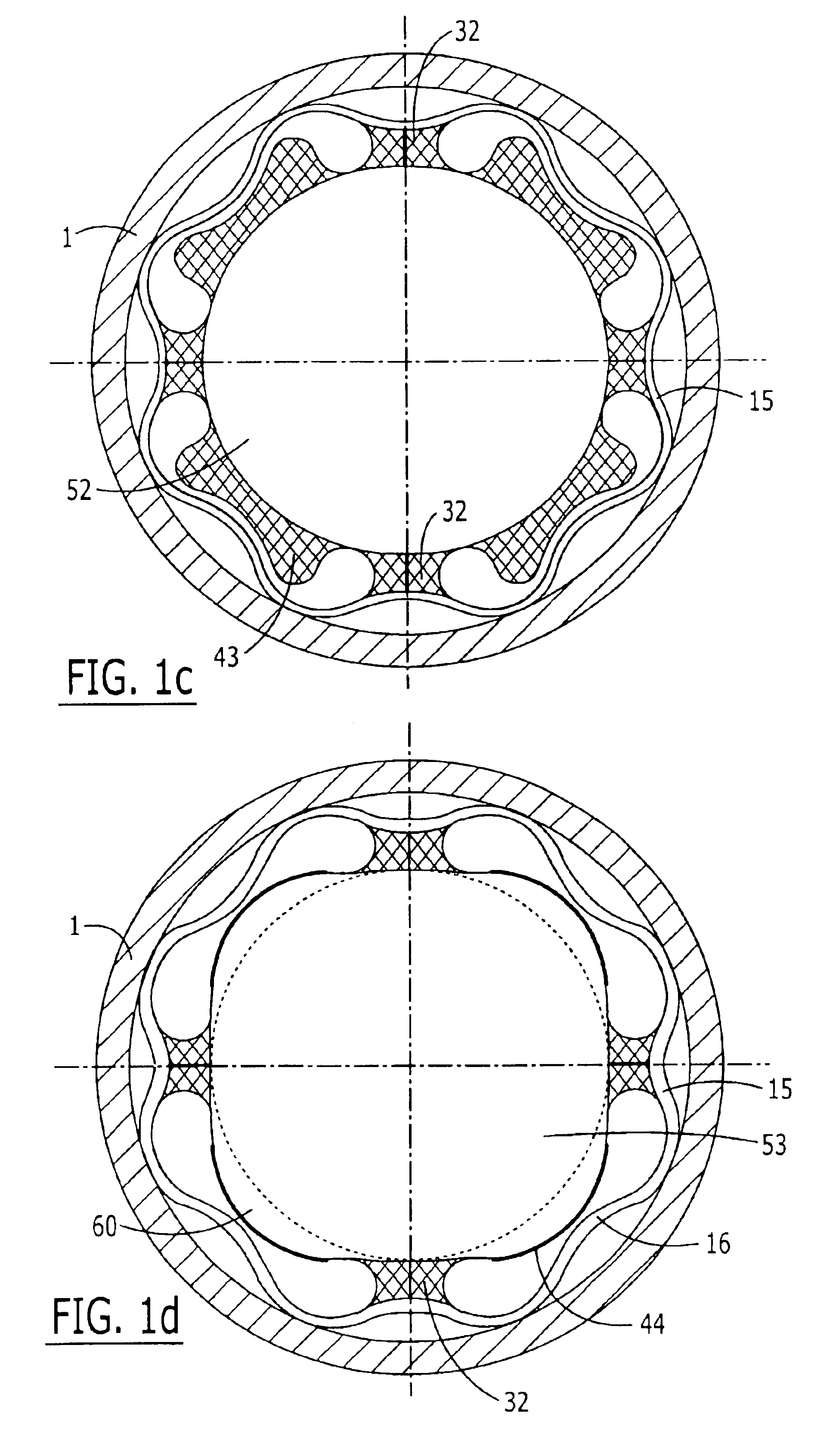
FIGS. 1a to 1d show, in cross section, four different exemplary embodiments of a vibration damper for a propeller shaft tube 1 such as is arranged, for example, in the drive train of a motor vehicle. The four vibration dampers each comprise a mass body 51-53 that is mounted centeredly via rubber spring elements 31, 32 in a sleeve 10, 15. The bonds between rubber spring elements 31, 32 and the respective sleeves 10, 15 as well as the mass bodies 51-53 belonging thereto are preferably created during vulcanization.

In the case of the exemplary embodiments shown in FIGS. 1a and 1b, sleeves 10 are of cylindrical configuration. Mass body 51 is a cylindrical tube. It is retained, for example, by four rubber spring elements 31 in each case. Arranged between each two supporting rubber spring elements 31 is a flexible rubber stop element 41. Stop element 41 of the exemplary embodiment shown in FIG. 1a is attached to mass body 51, while stop element 42 of the exemplary embodiment shown in FIG. ...


PUM

PropertyMeasurementUnit
inner radiusaaaaaaaaaa
massaaaaaaaaaa
flexibleaaaaaaaaaa

Abstract

A vibration damper for a tubular propeller shaft in the drive train of a motor vehicle having a mass body mounted concentrically, in the propeller shaft or in a sleeve attached in the propeller shaft, by way of at least one rubber spring element. Metal and/or flexible rubber stop elements that limit the vibration travel of the mass body at least in the radial direction are arranged between the mass body and the sleeve. Alternatively, the mass body and/or the sleeve are configured at least locally, in mutually opposite regions, as stop elements that limit the vibration travel of the mass body at least in the radial direction.

Description

FIELD OF THE INVENTIONThe present invention relates to a vibration damper for a tubular propeller shaft in the drive train of a motor vehicle having a mass body mounted concentrically in a sleeve by way of rubber spring elements, stop elements that limit the vibration travel of the mass body at least in the radial direction being arranged between the mass body and the sleeve.BACKGROUND OF THE INVENTIONGerman Patent DE 36 32 418 on the one hand describes a vibration damper whose mass body is attached directly in a hollow drive shaft by way of a rubber spring element which envelops it radially. Also described is a second vibration damper whose mass body is mounted in a sleeve by way of a rubber spring element which also envelops it. The sleeve is embedded in an elastic layer.The vibration dampers described there, also called cancelers, are installed principally in propeller shafts or propeller shaft tubes. The propeller shaft tubes are loaded on the one hand in torsion by the drive to...

Claims


Application Information

Patent Timeline
Patent Type & Authority Patents(United States)
IPC IPC(8): F16F1/36F16F1/371F16F15/10F16F15/14F16F1/38
CPCF16F1/371F16F1/3835F16F15/1442Y10T464/50F16C3/023F16C2326/06F16F15/10
Inventor LAUBLE, CHRISTIANMOSER, FRANZSCHLIMPERT, GUNTHERFLINSPACH, ROLAND
Owner DAIMLER AG
Why Eureka
Try Eureka