Eureka AIR delivers breakthrough ideas for toughest innovation challenges, trusted by R&D personnel around the world.

Image forming apparatus

Active Publication Date: 2011-01-27
KONICA MINOLTA BUSINESS TECH INC
View PDF0 Cites 8 Cited by
  • Summary
  • Abstract
  • Description
  • Claims
  • Application Information

AI Technical Summary

Benefits of technology

[0020]An object of the present invention is to improve the imbalance in amount of heat supplied to each portion of a sheet and the local wavy abrasion caused on the fixing roller, thereby providing an image forming apparatus which can achieve a long service life of a fixing roller without causing fixing unevenness and sheet wrinkles.

Problems solved by technology

On the other hand, if the fixing device is displaced on the condition that a sheet is held between a transfer section and the fixing device, new problems such as wrinkles on the sheet and image defects (insufficient fixing, unevenness in glossiness) due to imbalance of heat supplied to the sheet may occur.
Therefore, since it becomes necessary to employ the sheet conveying mechanism which is complicate and large in size, there are problems that cost increases and apparatus becomes large in size.
In Patent Document 2, since it is necessary to employ the position changing means to displace the entire body of a sheet in the width direction between the transfer section and the sheet feeding device, there are problems that cost increases and apparatus becomes large in size, as same as Patent document 1.
Further, since the temperature distribution of the fixing roller changes to a sheet which advances into the fixing device, the balance in amount of heat supplied to each portion of a sheet is not stabilized, fixing failures, such as fixing unevenness (gloss, degree of fixing) and sheet wrinkles may occur.
In Patent Documents 3, since the transfer fixing member is displaced relatively to a sheet in the width direction, due to the same reason as Patent Document 2, there are problems that fixing unevenness (gloss, degree of fixing) may occur on a toner image on a sheet.
Therefore, the image forming apparatus has some problems for practical use.

Method used


Image

  • Image forming apparatus
  • Image forming apparatus
  • Image forming apparatus

Examples


Embodiment Construction

[0039]Although the present invention is explained based on embodiments, the present invention is not limited to these embodiments. Further, this explanation does not limit the technical scope of claims and the meaning of terminology.

[Image Forming Apparatus]

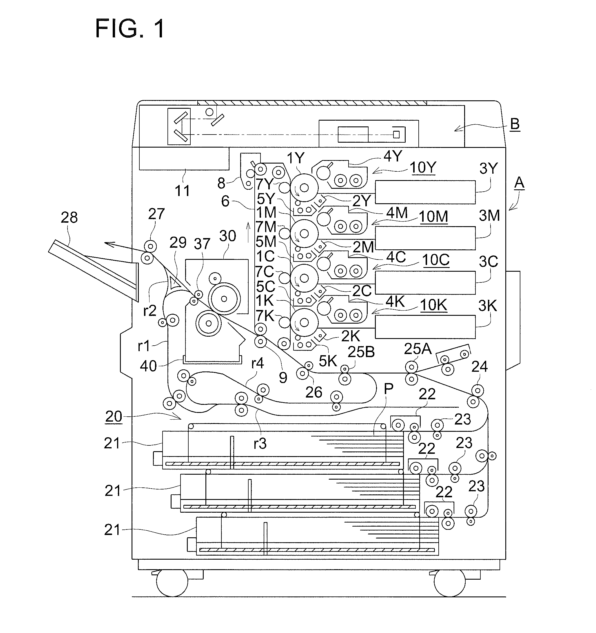
[0040]FIG. 1 is a structural view of an image forming apparatus A equipped with a fixing device according to the present invention.

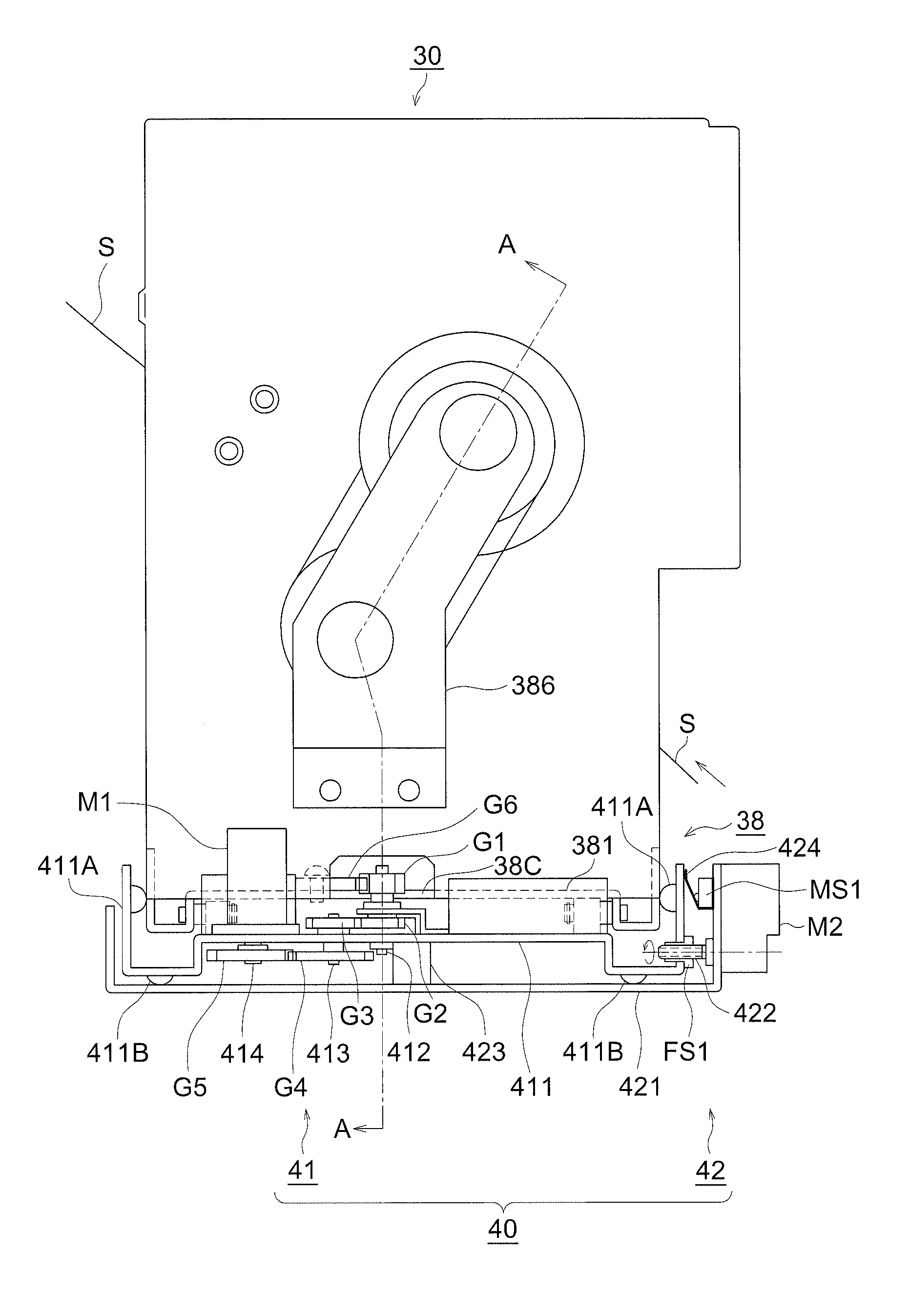
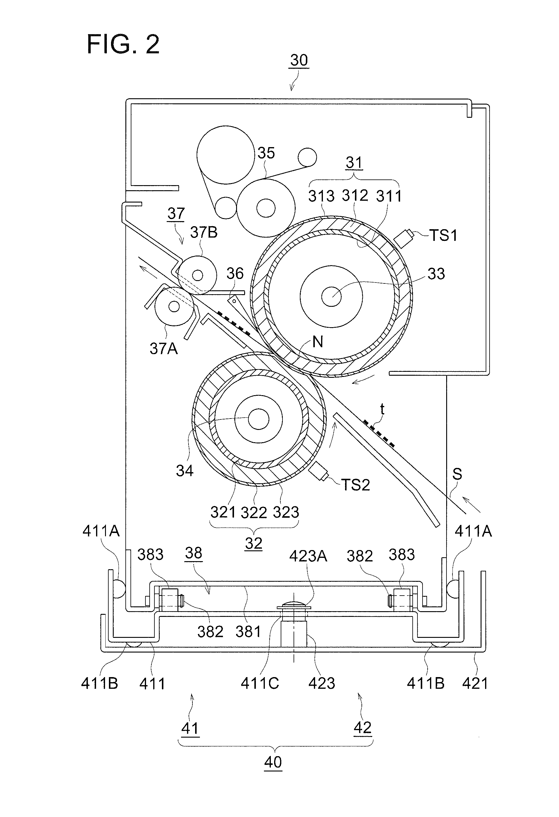
[0041]The image forming apparatus A is called a tandem type color image forming apparatus and is constituted with an image forming section 10, a sheet feeding device 20, and a fixing device 30. The image forming section 10 is constituted with plural sets of color image forming sections 10Y, 10M, 10C, and 10K and a transfer section.

[0042]On the upper part of the image forming apparatus A, provided is an image reading device B. An image on a document placed on a document stand is subjected to scanning exposure by an optical system of an image scanning exposing device of the image reading device B, and t...


PUM


Abstract

An image forming apparatus, comprises an image forming section; a pair of fixing members coming in pressure contact with each other so as to form a nip portion and to fix a toner image on a sheet conveyed from the image forming section with the nip portion; an oscillating section to oscillate the fixing members in a width direction perpendicular to a sheet conveying direction; an inclining section to incline the fixing members to the width direction in parallel to a conveyance surface; and a control section to control the oscillating section and the inclining section such that when a sheet is passing through the nip portion, a direction of a one-sided oscillation shift of the sheet due to the oscillation of the fixing members is made opposite to that of a one-sided inclination shift of the sheet due to the inclination of the fixing members.

Description

[0001]This application is based on Japanese Patent Application No. 2009-169897 filed on Jul. 21, 2009, in Japanese Patent Office, the entire content of which is hereby incorporated by reference.BACKGROUND OF THE INVENTION[0002]The present invention relates to a fixing device and an image forming apparatus which fix an image formed on a sheet.[0003]In recent years, in electro-photographic type image forming apparatuses, such as printers and digital composite machines, demands of commercial markets become strong for a performance capable of outputting images with high quality in large amounts at high speed and the longer service life of components associated with the electro-photographic process.[0004]In order to respond to such demands of commercial markets, desired is a technique to disperse positions where the edge portions of a sheet comes in contact with the surface of a fixing roller, by oscillating a fixing device in the width direction of the sheet when the sheet passes throug...

Claims


Application Information

Patent Timeline
IPC IPC(8): G03G15/20
CPCG03G15/2064
Inventor NAGASE, HISAYOSHIFUNABIKI, HIROSHI
Owner KONICA MINOLTA BUSINESS TECH INC
Why Eureka
Eureka Blog
Learn More