Teaching device for robots, robot using same, and robot operating method

a robot and teaching device technology, applied in the direction of electric programme control, program control, instruments, etc., can solve the problems of increasing the difficulty of the operator in adjusting the position of the robot in continuous operation, the danger of accidents, and the collision between the robot and the object, so as to reduce the number of operation keys, reduce the cost, and miniaturize the teaching device

Inactive Publication Date: 2001-11-29
PANASONIC CORP
View PDF0 Cites 54 Cited by
  • Summary
  • Abstract
  • Description
  • Claims
  • Application Information

AI Technical Summary

Benefits of technology

0027] (ii) a step of controlling the operation speed of the robot arm by rotating the jog dial in a state that the jog dial is neither pushed nor pulled, and a step of controlling the position of the robot arm by rotating the jog dial in a state that the jog dial is either pushed or pulled at least.
0028] With this configuration, the number of operation keys can be decreased, making it possible to realize cost reduction and to miniaturize the teaching device. Further, the working efficiency and the operational safety may be considerably proved. In addition, it is possible to readily control the operations of the robot ranging from delicate positioning to high-speed continuous operation by serial manipulations. As a result, the working efficiency and the operational safety can be greatly enhanced.

Problems solved by technology

On the contrary, when the robot approaches an object and is required to make a narrow move, there is a danger of accidents such as collision between the robot and the object if the robot is still operated at a high speed.
And, when the robot further approaches the object and is required to make a delicate move, it becomes extremely difficult for the operator to adjust the position of the robot in continuous operation.
However, in the above configuration of the prior art, frequent changing of the speed makes the manipulation complicated.
Moreover, the operator is liable to make mistakes in selecting the speed.
Further, the operator has to carry out the job frequently changing the mode to and from the continuous operation and pitch operation while still frequently selecting the operation speed and moving amount in the respective modes.
Accordingly, these operations make the manipulation complicated, worsening the working efficiency, and also causes generation of faulty manipulation.

Method used


Image

  • Teaching device for robots, robot using same, and robot operating method
  • Teaching device for robots, robot using same, and robot operating method

Examples


exemplary embodiment 1

[0089]

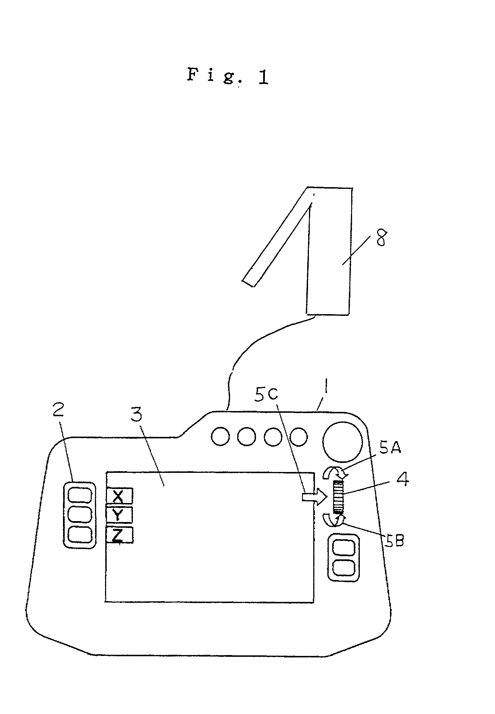
[0090] FIG. 1 shows an embodiment of a teaching device (teaching pendant) for robots of the present invention.

[0091] In FIG. 1, teaching pendant 1 is electrically connected to robot 8. There are provided a plurality of operation keys 2 at the left side of the teaching pendant 1. The plurality of operation keys 2 include operation keys which are same in number to the degree of freedom of movement of the robot, and in the present example are shown the degrees of freedom in three operational directions, X axis, Y axis, and Z axis.

[0092] The plurality of operation keys 2 also serve a function as an operation permit key. That is, the operation keys 2 are provided with a function as an operation permit key to prevent the robot from operating with an operation button pressed by mistake at the same time when designating the operational direction. As an operation key to serve these respective functions, an ever-open type switch is employed.

[0093] Also, the operation key 2 is a function...

exemplary embodiment 2

[0124]

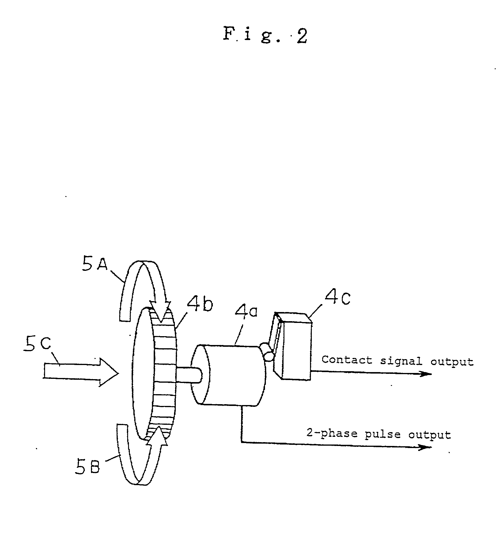
[0125] In the above exemplary embodiment 1, the configuration provides a function such that the jog dial 4 can be pushed in, but it is not limited only to this configuration. It is also possible to provide a function such that the jog dial 4 can be pulled.

[0126] That is, when the jog dial is rotated in a state that the jog dial is not pulled, the position of the robot arm can be controlled by the rotation of the jog dial, and when the jog dial is rotated in a state that the jog dial is pulled, the operation speed of the robot arm can be controlled by the rotation of the jog dial.

[0127] Also, the controller comprises a rotation detector which detects the rotated state of the jog dial, a pressure detector which detects the pushed state of the jog dial, and a judging means.

[0128] The judging means receives the input signal from the rotation detector and pressure detector, and when the jog dial is rotated in a state that the jog dial is not pulled, the signal from the rotation det...


PUM


Abstract

The number of operation keys is decreased, realizing cost reduction and miniaturization of a teaching device. Further, the working efficiency and operational safety are considerably improved. Also, the operations of the robot ranging from delicate positioning and high-speed continuous operation can be readily controlled by serial manipulations. The present invention includes (a) a plurality of operation keys to designate one out of a plurality of operation coordinates of the robot arm, and (b) a controller which controls the operation of the robot arm. The controller has a function to control the robot arm so that the robot arm is positioned on the designated operation coordinates and also a function to control the operation speed of the robot arm. The controller includes a jog dial disposed in a manner such that the jog dial can be rotated and pushed. When the jog dial is rotated in a state that the jog dial is not pushed, the position of the robot arm is controlled by the rotation of the jog dial, and when the jog dial is rotated in a state that the jog dial is pushed, the operation speed of the robot arm is controlled by the rotation of the jog dial.

Description

FIELD OF THE INVENTION[0001] The present invention relates to a teaching device for robots, a robot using the teaching device, and a method of operating a robot.BACKGROUND OF THE INVENTION[0002] Conventionally, a robot is operated by manipulating a plurality of keys disposed in a teaching device (teaching pendant).[0003] In this case, the basic keys to operate the robot comprise a plurality of keys including two keys, normal and reverse keys, disposed on the respective operation coordinates of a plurality of operation coordinates, and an operation permit key to prevent accidental operation of the robot due to wrong manipulation of an operation button. In such conventional robot, the operator presses an operation key corresponding to the desired direction while pressing the operation permit key, and thereby, the robot is operated in a continuous operation mode.[0004] In that case, when the robot is widely moved, for example, by dozens of centimeters in distance, it is necessary to op...

Claims


Application Information

Patent Timeline
Patent Type & Authority Applications(United States)
IPC IPC(8): B25J9/22B25J9/10B25J13/02B25J13/06G05B19/42
CPCB25J13/06G05B2219/36005B25J13/02
Inventor MUKAI, YASUSHI
Owner PANASONIC CORP
Why Eureka
Try Eureka