Supercharge Your Innovation With Domain-Expert AI Agents!

Bridge crane and sliding contact line dust cleaning device thereof

A technology of bridge crane and cleaning device, which is applied in the direction of transportation and packaging, cleaning methods and appliances, cleaning methods using gas flow, etc., which can solve problems such as high safety risks, affecting the production of metallurgical plants, and large losses due to production stoppages, so as to achieve safety High safety, the effect of preventing personal injury accidents

Inactive Publication Date: 2020-07-03
攀钢集团西昌钢钒有限公司
View PDF6 Cites 0 Cited by
  • Summary
  • Abstract
  • Description
  • Claims
  • Application Information

AI Technical Summary

Problems solved by technology

When the metal dust falling from the factory building is deposited on the trolley line too much, it will cause the insulation medium of the trolley line to be greatly reduced. Burning out will eventually cause the bridge crane to have no power source and cannot carry out lifting work, which will directly affect the production of the metallurgical plant. Therefore, it is very important to clean the metal dust on the trolley line in time
[0004] At present, the method of cleaning the trolley line in the metallurgical plant is mostly: the whole span is planned to stop production for 3 to 4 hours, and about 20 maintenance personnel are distributed in sections of two people on the crane walking platform above the entire span trolley line of the plant. After the shutdown order and a power outage across the entire span, maintenance personnel in groups of two carried safety belts and went down to the trolley line at a height of about 25 meters. The method is time-consuming and labor-intensive, the loss of production shutdown is large, and the safety risk is high

Method used


Image

  • Bridge crane and sliding contact line dust cleaning device thereof
  • Bridge crane and sliding contact line dust cleaning device thereof

Examples


Embodiment Construction

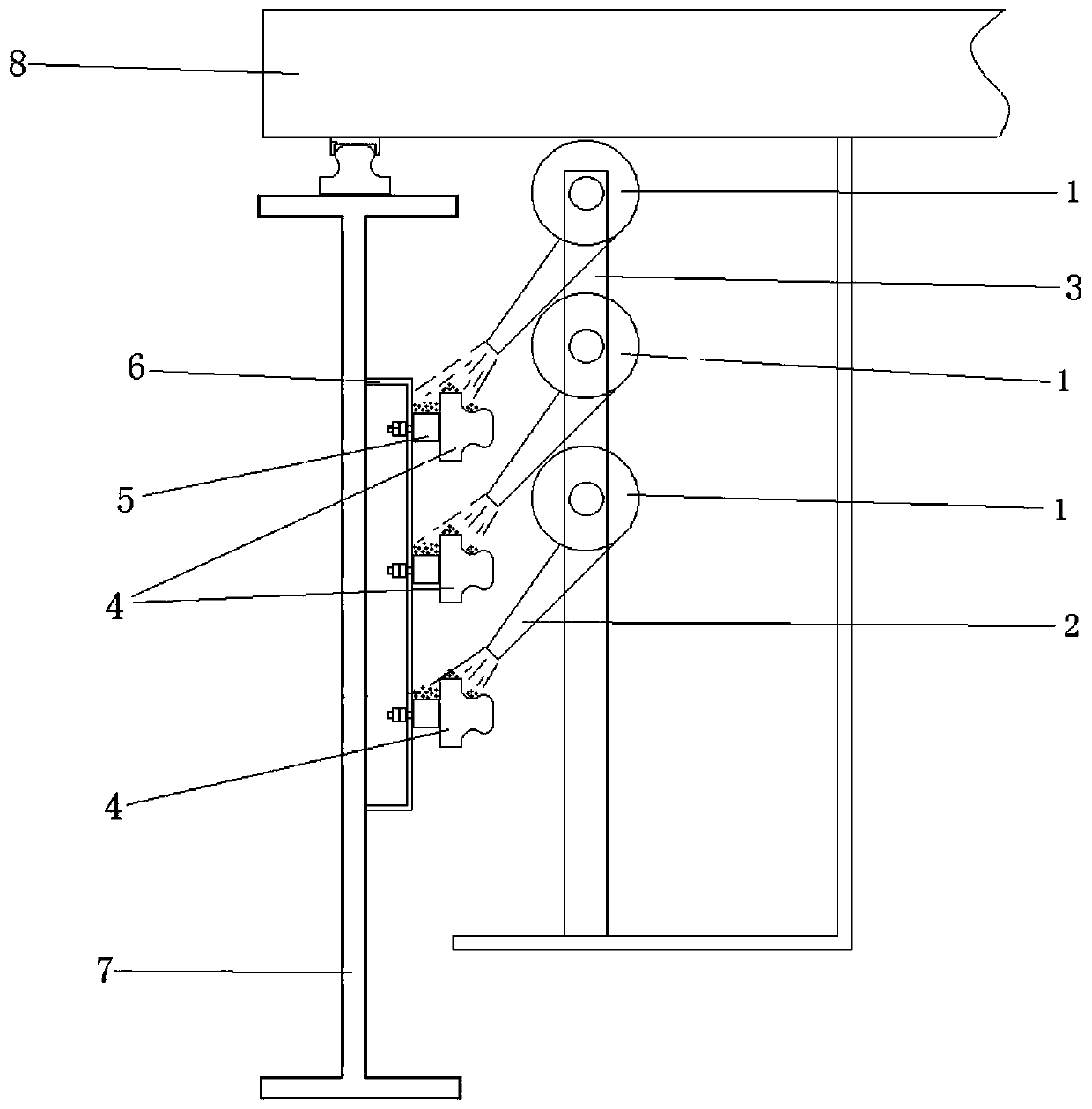
[0022] The core of the present invention is to provide a trolley line dust cleaning device of a bridge crane, which can clean the dust on the trolley line without stopping the crane, which saves time and labor and has high safety. Another core of the present invention is to provide an overhead crane including the above-mentioned dust cleaning device.

[0023] In order to enable those skilled in the art to better understand the solution of the present invention, the present invention will be further described in detail below in conjunction with the accompanying drawings and specific embodiments.

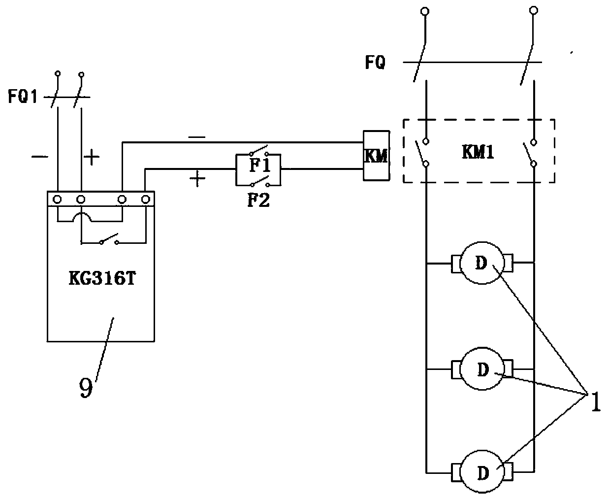
[0024] Please refer to figure 1 and figure 2 , figure 1 It is a side view of a specific embodiment of the trolley line dust cleaning device provided by the present invention; figure 2 It is an electrical control diagram of a specific embodiment of the trolley line dust cleaning device provided by the present invention.

[0025] The trolley line dust cleaning device of the bridge...


PUM


Abstract

The invention discloses a sliding contact line dust cleaning device of a bridge crane. The sliding contact line dust cleaning device of the bridge crane comprises a bracket which is fixed on a cart walking part of the crane and an air blowing device which is mounted on the bracket, and an air outlet of the air blowing device is aligned with the upper surface of a sliding contact line. According tothe sliding contact line dust cleaning device of the bridge crane, the air blowing device is started after being electrified to blow air to the sliding contact line to blow off dust deposited on thesliding contact line, and when the bridge crane moves back and forth along a track, the air blowing device is driven to move along the length direction of the sliding contact line, so that the fact the the whole sliding contact line is cleaned by utilizing the air blowing device is realized; and by utilizing the sliding contact line dust cleaning device, the metal dust on the sliding contact lineof the bridge crane can be automatically cleaned under the condition that the crane is not stopped, so that time and labor are saved, and meanwhile, personal injury accidents caused by manual cleaningof the sliding contact line are avoided. The invention further discloses the bridge crane comprising the sliding contact line dust cleaning device.

Description

technical field [0001] The invention relates to the technical field of dust cleaning in the metallurgical industry, in particular to a dust cleaning device for trolley lines of bridge cranes. In addition, the present invention also relates to an overhead crane including the above trolley line dust cleaning device. Background technique [0002] At present, in the smelting and production process of the metallurgical industry, a large amount of insurmountable metal dust will be produced. After floating in the metallurgical plant for a certain period of time, the metal dust will slowly land on various parts of the plant. [0003] The bridge crane is the equipment for lifting and transporting the workpiece in the metallurgical plant. It is completely driven by electric power. It is in frictional contact. When supplying power, the power is first transmitted to the trolley line, and then the power on the trolley line is transmitted to the crane through the collector that slides an...

Claims


Application Information

Patent Timeline
IPC IPC(8): B08B5/02B08B13/00B66C13/12
CPCB08B5/02B08B13/00B66C13/12
Inventor 邓洪兵唐勇
Owner 攀钢集团西昌钢钒有限公司
Features
  • R&D
  • Intellectual Property
  • Life Sciences
  • Materials
  • Tech Scout
  • Unparalleled Data Quality
  • Higher Quality Content
  • 60% Fewer Hallucinations
Learn More