
A foot pedal automatic air return device

A pedal and automatic technology, applied in transportation and packaging, mechanical conveyors, conveyors, etc., can solve problems such as increasing the labor intensity of operators, reducing the speed of vehicle assembly, and affecting the production efficiency of the production line

Active Publication Date: 2021-07-06
一汽丰田汽车(成都)有限公司
View PDF0 Cites 0 Cited by
  • Summary
  • Abstract
  • Description
  • Claims
  • Application Information

AI Technical Summary

Problems solved by technology

[0003] When assembling the pedals of the whole vehicle, the operator needs to take the pedals from the shelf, but the existing pedal shelves are made of fixed wire rods. In order to protect the pedals from bumping and damage, in order It is convenient for the transfer of the foot pedal, the foot pedal is placed on the auxiliary pallet, and after the operator takes the foot pedal, the pallet needs to be manually returned to empty, and the pallet needs to be bent by the operator greatly and frequently waist, which greatly increases the labor intensity of operators, reduces the speed of vehicle assembly, and affects the production efficiency of the entire production line

Method used


Image

  • A foot pedal automatic air return device
  • A foot pedal automatic air return device
  • A foot pedal automatic air return device

Examples


Embodiment 1

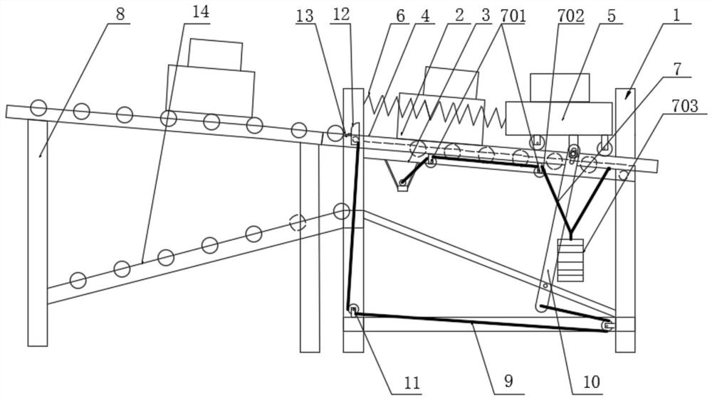
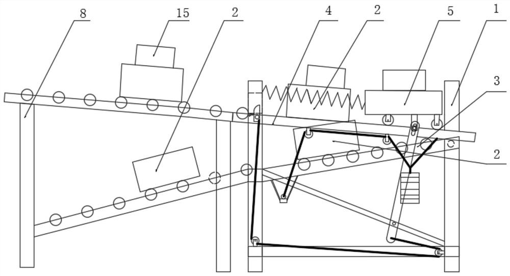
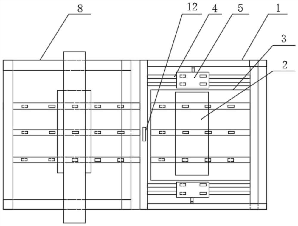
[0024] Such as Figure 1~3 As shown, a foot pedal 15 automatic air return device includes a first material conveying platform 1 and a pallet 2; Material plate 3; the conveying surface of the first material conveying platform 1 is set with a high left and a low right, and in the width direction of the first material conveying platform 1, support stations are provided on both sides of the right end, and between the support stations It is a cavity, and the distance in the width direction of the cavity is greater than the width of the pallet 2; the right end of the discharge plate 3 is hinged with the first material conveying platform 1; the discharge plate 3 is located below the cavity; the pallet 2 carries the pedal 15 Enter from the left side of the first material conveying platform 1: the tray 2 slides along the conveying surface of the first material conveying platform 1, the pedal 15 on the tray 2 slides along the top of the first material conveying platform 1 to the support...

Embodiment 2

[0028] Such as Figure 1~3 As shown, this embodiment is further limited on the basis of Embodiment 1: a foot pedal 15 automatic air return device, the top of the first material conveying platform 1 is provided with two slide rails 4 with a left high and a right low slope, the two The slide rails 4 are parallel to each other and arranged at intervals on the top of the first material conveying platform 1, two slide rails 4 are arranged on both sides of the unloading plate 3, and the projection on the vertical direction of the slide rails 4 is in line with the length direction of the first material conveying platform 1. Parallel; there is a trolley 5 on the slide rail 4, the trolley 5 provides a support station for the pedal 15, and can slide along the length direction of the slide rail 4, and the trolley 5 is always located on the slide rail 4 under the action of no external force Left end; the tray 2 carries the pedal 15 and enters from the left side of the first material conve...


PUM


Abstract

The invention discloses an automatic emptying device for pedals, which includes a first material conveying platform and a tray; the tray is used to carry the pedals, the length of the pedals is greater than the width of the tray, and a discharge plate is also included; the first The conveying surface of a material conveying platform is set to be high on the left and low on the right. In the width direction of the first material conveying platform, supporting stations are provided on both sides of the right end. There is a cavity between the supporting stations, and the width of the cavity is The direction spacing is greater than the width of the pallet; the right end of the unloading plate is hinged to the first material conveying platform; the unloading plate is located below the cavity; the setting of the inclined setting of the first material conveying platform and the setting that the unloading plate can rotate around the hinge shaft , no external power source is needed to automatically separate the tray and the foot pedal, and the tray is automatically returned to empty, replacing the manual emptying of the tray by the operator, without the need for the operator to bend over significantly and frequently, reducing the labor intensity of the operator and improving the overall performance. vehicle assembly efficiency.

Description

technical field [0001] The invention relates to the field of tooling for auto parts, in particular to an automatic air return device for pedals. Background technique [0002] The automobile assembly workshop has a large area. On the automobile assembly line, a large number of auto parts are placed on the station rack. The parts are placed for easy access. Generally, the parts are placed in the area corresponding to the assembly station on the production line; for example: Vehicles to be assembled are placed on both sides of the wheel assembly station on the production line. [0003] When assembling the pedals of the whole vehicle, the operator needs to take the pedals from the shelf, but the existing pedal shelves are made of fixed wire rods. In order to protect the pedals from bumping and damage, in order It is convenient to transfer the pedals, the pedals are placed on the auxiliary pallet, and after the operator takes the pedals, the pallet needs to be manually returned ...

Claims


Application Information

Patent Timeline
Patent Type & Authority Patents(China)
IPC IPC(8): B65G37/02
CPCB65G37/02
Inventor 李小勇
Owner 一汽丰田汽车(成都)有限公司
Learn More