
Welding fixture sharing upper counterweight frame and lower counterweight frame

A welding tooling and counterweight frame technology, applied in welding equipment, auxiliary welding equipment, welding/cutting auxiliary equipment, etc., can solve problems such as cumbersome, difficult to ensure accuracy, and production errors

Pending Publication Date: 2020-07-07
XUANCHENG VALIN PRECISION TECH
View PDF0 Cites 0 Cited by
  • Summary
  • Abstract
  • Description
  • Claims
  • Application Information

AI Technical Summary

Problems solved by technology

[0002] During the installation of the elevator, counterweights should be used to balance the weight of the car. The counterweights are a combination of many blocks stacked together. During installation, there is a counterweight frame on the upper and lower sides, which are the upper counterweight frame and the lower counterweight frame respectively. frame, the two counterweights are assembled by flat plate welding. In the past, the welding work needed to be done manually, and it was difficult to guarantee the accuracy
[0003] The use of welding equipment can reduce the tediousness of the work, but because the shapes of the upper counterweight frame and the lower counterweight frame are not exactly the same, a set of welding equipment cannot be shared
It is very cumbersome to manufacture two kinds of welding tools separately. At the same time, because the size of the two is not much different, misoperations are often caused in production, and inappropriate tooling is selected for mixed use, resulting in production errors.

Method used


Image

  • Welding fixture sharing upper counterweight frame and lower counterweight frame
  • Welding fixture sharing upper counterweight frame and lower counterweight frame
  • Welding fixture sharing upper counterweight frame and lower counterweight frame

Examples


Embodiment Construction

[0022] The technical solution of the present invention will be further explained below in conjunction with the accompanying drawings.

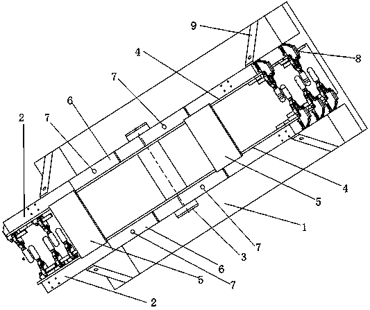
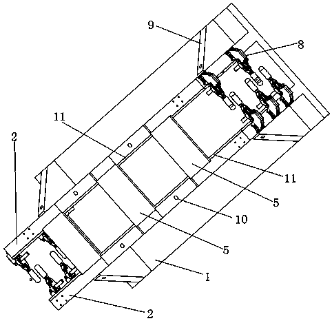
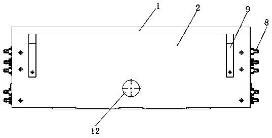
[0023] A welding tool shared by the upper and lower counterweight frames. The counterweight frame includes two types: an upper counterweight frame and a lower counterweight frame, which are installed on the upper and lower parts of the counterweight respectively. Both the upper counterweight frame and the lower counterweight frame include two It is a parallel and facing flat plate. The side of the flat plate is welded and connected by several connecting bars to form a U shape. The two flat plates of the lower counterweight frame are complete, and the two flat plates of the upper counterweight frame are pierced with round holes. The upper counterweight frame The plate width is greater than the plate width of the lower counterweight frame, and the plate length of the upper counterweight frame is equal to the plate length of the lower counterweigh...


PUM


Abstract

The invention discloses a welding fixture sharing an upper counterweight frame and a lower counterweight frame. The welding fixture is formed by connecting a base plate and two vertical plates which are perpendicular to the base plate; the lengths of the base plate and the vertical plates are consistent with the length of the upper counterweight frame or the lower counterweight frame; the heightsof the vertical plates are greater than the width of a panel of the lower counterweight frame, and is less than the width of a panel of the upper counterweight frame; through circular holes corresponding to the position of a circular hole of the upper counterweight frame are formed in the vertical plates; a pin rod is matched with the circular holes in diameter; when the lower counterweight frameis fixed, the panel of the lower counterweight frame is aligned with the outer sides of the vertical plates; a plurality of connecting strips are pressed against the panel of the lower counterweight frame and the side plates of the vertical plates; when the upper counterweight frame is fixed, the panel of the upper counterweight frame is aligned with the inner sides of the vertical plates; the outer side of the panel of the upper counterweight frame exceeds the vertical plates; the pin rod penetrates through the circular holes and is locked; and extending base plates are mounted on the side surfaces of the vertical plates. By using the welding fixture, welding and positioning can be performed accurately; measurement and alignment are not required to be performed; and in addition, the uppercounterweight frame and the lower counterweight frame can be shared, so that the reliability is improved.

Description

technical field [0001] The invention relates to a welding tool, in particular to a welding tool shared by upper and lower counterweight frames. Background technique [0002] During the installation of the elevator, counterweights should be used to balance the weight of the car. The counterweights are a combination of many blocks stacked together. During installation, there is a counterweight frame on the upper and lower sides, which are the upper counterweight frame and the lower counterweight respectively. The frame and the two counterweights are assembled by plate welding. In the past, the welding work needed to be done manually, and it was difficult to guarantee the accuracy. [0003] The use of welding equipment can reduce the cumbersomeness of the work, but because the shapes of the upper counterweight frame and the lower counterweight frame are not exactly the same, a set of welding equipment cannot be shared. It is very cumbersome to manufacture two kinds of welding ...

Claims


Application Information

Patent Timeline
IPC IPC(8): B23K37/04
CPCB23K37/0435
Inventor 黄业华张强阎娟
Owner XUANCHENG VALIN PRECISION TECH
Learn More