A stirrup device for rebar

A technology of rebar and stirrup, applied in application, household appliances, other household appliances, etc., can solve the problems of time-consuming rebar, difficulty in keeping the distance between stirrups, and labor intensity of workers, so as to achieve reliable stirrups and reduce work. Fatigue strength, the effect of reducing manual workload

Active Publication Date: 2020-10-16
高唐融知融智科技服务有限公司
View PDF9 Cites 0 Cited by
  • Summary
  • Abstract
  • Description
  • Claims
  • Application Information

AI Technical Summary

Problems solved by technology

[0002] The most consumed steel on the construction site is rebar, which needs to be used for foundation construction, so it needs to increase the strength, four threaded rods are a unit, and the four rebars need to be fixed by stirrups, and each distance needs stirrups It is very time-consuming to stirrup the rebar every time, and the labor intensity of the workers is very high. Since the position of the stirrup is manually measured and then marked and then the stirrup is made, it is difficult to make the distance of the stirrup of each section consistent.

Method used


Image

  • A stirrup device for rebar
  • A stirrup device for rebar
  • A stirrup device for rebar

Examples


Embodiment Construction

[0020] All features disclosed in this specification, or steps in all methods or processes disclosed, may be combined in any manner, except for mutually exclusive features and / or steps.

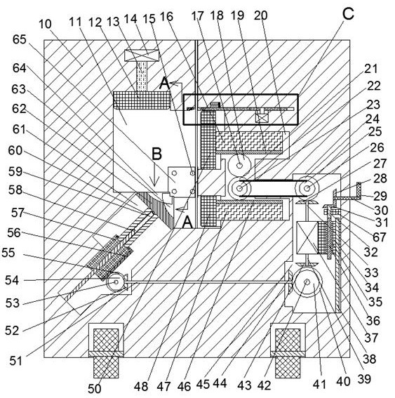
[0021] Combine below Figure 1-5 The present invention is described in detail, and for convenience of description, the orientations mentioned below are now stipulated as follows: figure 1 The up, down, left, right, front and back directions of the projection relationship itself are the same.

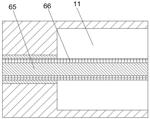
[0022] A stirrup device for threaded steel of the device of the present invention comprises an outer casing 10, a support block 65 is fixedly installed in the middle of the outer casing 10, and four threaded steel support holes 15 are arranged in the support block 65 , the threaded steel support hole 15 runs through the outer casing 10, the outer casing 10 is provided with a compacting chamber 11, and the upper part of the compacting chamber 11 is communicated with an insertion chamber 71 with an openin...


PUM


Abstract

The invention discloses a stirrup device for threaded steel, comprising an outer casing, a support block is fixedly installed in the middle of the outer casing, four threaded steel support holes are arranged in the support block, and the threaded steel The supporting hole runs through the outer casing, and a compression cavity is arranged in the outer casing, and an insertion cavity with an opening facing upwards is communicated above the compression cavity, and a sliding cavity is communicated with a sliding cavity below the compression cavity. The opening of the tightening chamber faces backward, and the right side of the compacting chamber is connected with a moving chamber, and a shearing chamber is arranged above the moving chamber, and a transmission chamber connected with the compacting chamber is arranged below the moving chamber, and the transmission chamber is connected with the compacting chamber. There is a transmission component in the cavity. This device automatically stirrups the four rebars on the foundation of the building, which reduces the manual workload and reduces the fatigue strength of manual work, and the stirrups are more reliable. Due to the mechanical movement Manual measurement is avoided, and the position is more accurate.

Description

technical field [0001] The invention relates to the technical field of building steel, in particular to a stirrup device for threaded steel. Background technique [0002] The most consumed steel on the construction site is rebar, which needs to be used for foundation construction, so it needs to increase the strength, four threaded rods are a unit, and the four rebars need to be fixed by stirrups, and each distance needs stirrups It is very time-consuming to stirrup the rebar every time, and it is very labor-intensive for the workers. Since the position of the stirrups is manually measured and then marked and then the stirrups are made, it is difficult to make the distance of each section of the stirrups consistent. [0003] The present application describes a stirrup device for threaded steel, which can solve the above problems. Contents of the invention [0004] Aiming at the deficiencies of the above-mentioned technologies, the present invention proposes a stirrup devi...

Claims


Application Information

Patent Timeline
Patent Type & Authority Patents(China)
IPC IPC(8): B21F27/20B21F1/00B21F11/00
CPCB21F1/00B21F11/00B21F27/20
Inventor 戴凤
Owner 高唐融知融智科技服务有限公司
Why Eureka
Try Eureka