
Toy driving system and toy car

A technology for a drive system and a toy, applied in the field of a toy drive system and a toy car, can solve the problems of unfavorable toy car manufacturing, structural complexity of toy cars, and high cost of toy car manufacturing

Active Publication Date: 2020-07-14
ALPHA GRP CO LTD +1
View PDF8 Cites 1 Cited by
  • Summary
  • Abstract
  • Description
  • Claims
  • Application Information

AI Technical Summary

Problems solved by technology

[0003] However, both of these two technical solutions need to be equipped with two driving devices, resulting in high manufacturing cost of the toy car, and the steering mechanism in the second solution not only increases the cost, but also increases the structural complexity of the toy car, which is not conducive to the production and manufacture of the toy car

Method used


Image

  • Toy driving system and toy car
  • Toy driving system and toy car
  • Toy driving system and toy car

Examples


Embodiment 1

[0051] like Figure 3-10 Shown is a schematic diagram of the driving system of the toy in Embodiment 1 of the present invention.

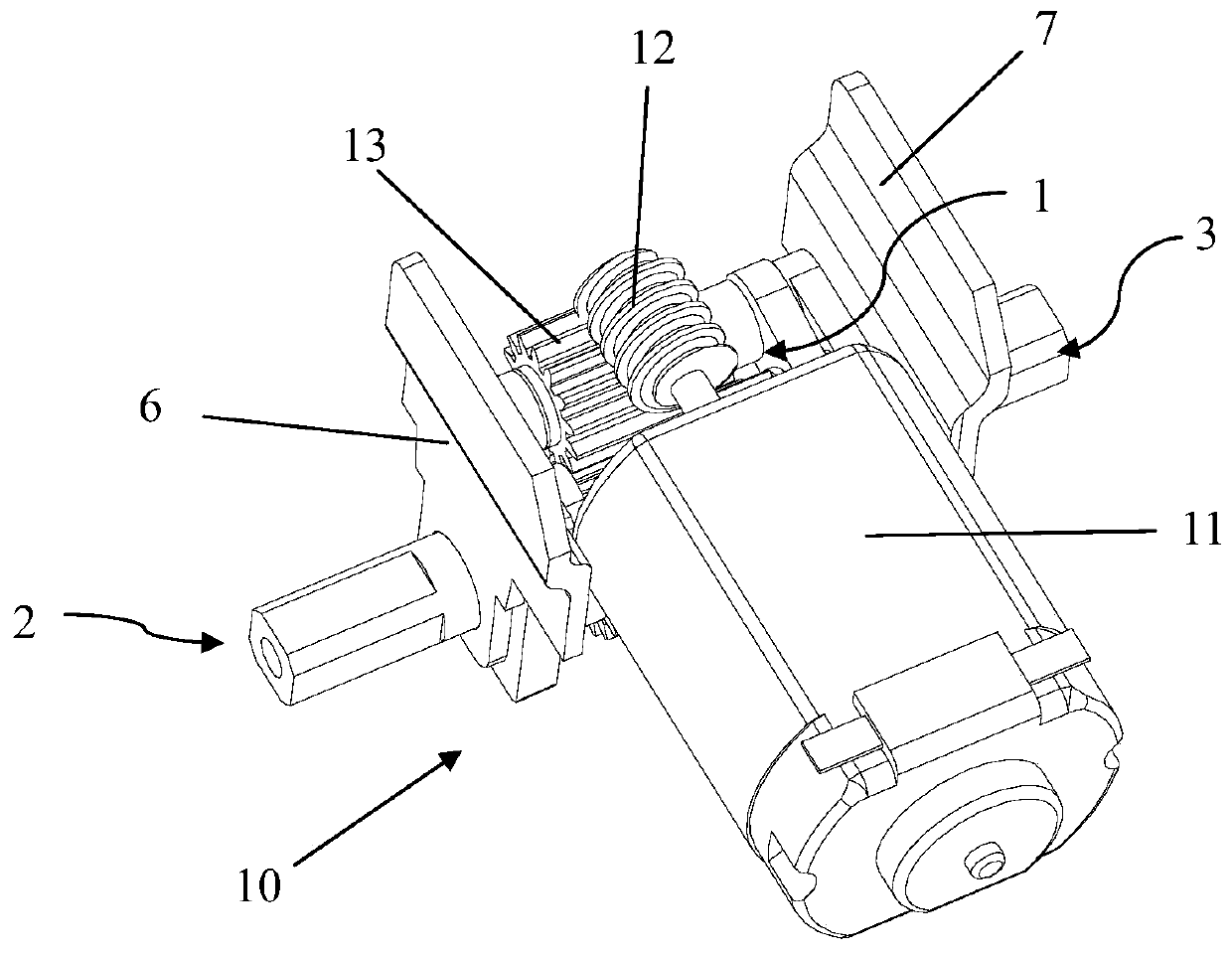
[0052] like Image 6 As shown, the toy driving system 10 includes a power unit 1, a first output mechanism 2 and a second output mechanism 3, and also includes a clutch transmission mechanism 4 and a one-way transmission mechanism 5. The connection between the first output mechanism 2 and the second output mechanism 3 A one-way transmission mechanism 5 is connected between them, and the one-way transmission mechanism 5 transmits the power from the first output mechanism 2 to the second output mechanism 3 in one direction, and the clutch transmission mechanism 4 is connected between the power unit 1 and the second output mechanism 2;

[0053] When the power unit 1 rotates in the first direction, the power unit 1 drives the first output mechanism 2 to rotate, and the power unit 1 drives the second output mechanism 3 to rotate through the clutch tran...

Embodiment 2

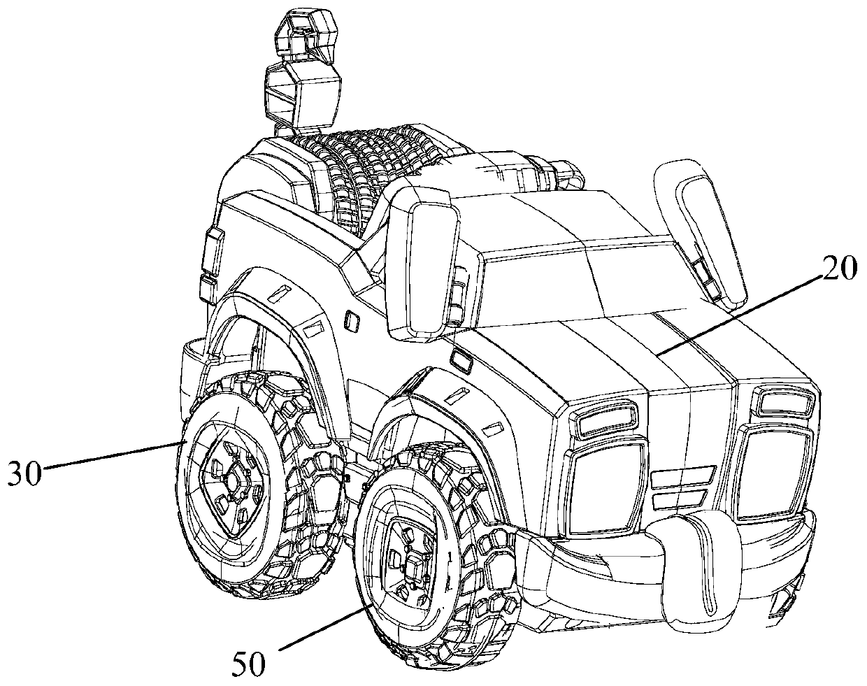
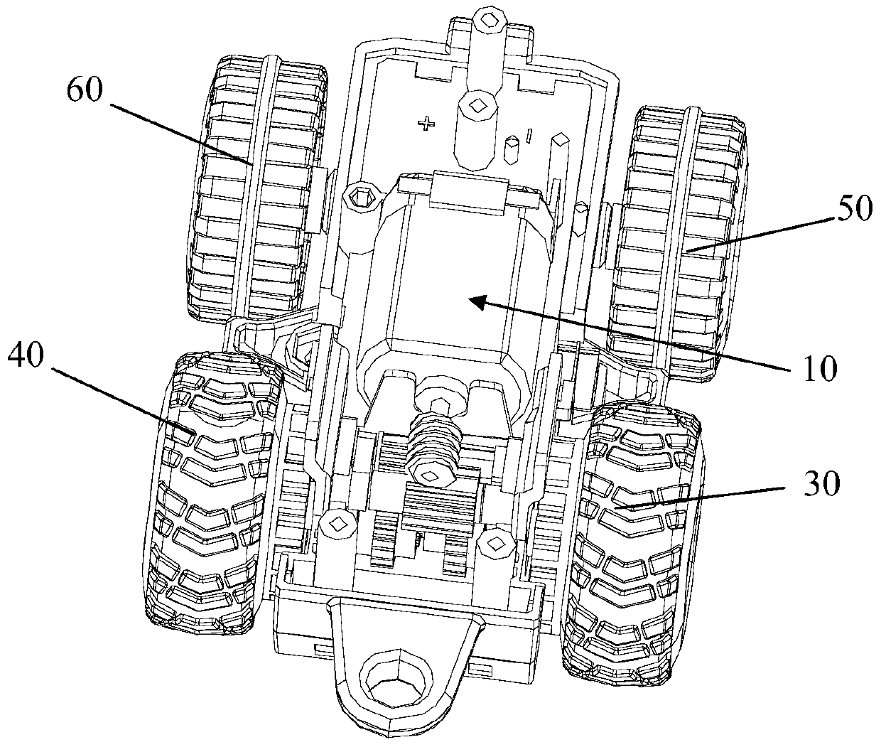
[0124] like Figure 1-2 As shown, the toy car includes a car body 20, a first driving wheel 30 and a second driving wheel 40, and also includes a toy driving system 10. The first output mechanism 2 is connected to the first driving wheel 30, and the second output mechanism 3 is connected to the second driving wheel 40. The drive wheel 40 is connected.

[0125] Wherein, the first driving wheel 30 and the second driving wheel 40 are located at the rear of the car, and the toy car also includes a front right wheel 50 and a front left wheel 60 at the front of the car.

[0126] The toy drive system 10 is installed in the vehicle body 20 and is located near the rear of the vehicle. Wherein, the first output mechanism 2 is connected with the first driving wheel 30 , and the second output mechanism 3 is connected with the second driving wheel 40 .

[0127] When the first output mechanism 2 and the second output mechanism 3 rotate in the same direction, the first driving wheel 30 and...


PUM


Abstract

The invention discloses a toy driving system. The toy driving system comprises a power unit, a first output mechanism and a second output mechanism, the clutch transmission mechanism and the one-way transmission mechanism are further included, the one-way transmission mechanism is connected between the first output mechanism and the second output mechanism, the one-way transmission mechanism transmits power from the first output mechanism to the second output mechanism in a one-way mode, and the clutch transmission mechanism is connected between the power unit and the second output mechanism;when the power unit rotates in the first direction, the power unit drives the first output mechanism to rotate, the power unit drives the second output mechanism to rotate through the clutch transmission mechanism, the one-way transmission mechanism does not transmit, and the first output mechanism and the second output mechanism rotate in opposite directions. When the power unit rotates in the second direction, the first output mechanism is driven to rotate, the clutch transmission mechanism is separated from the second output mechanism, the first output mechanism transmits power to the second output mechanism through the one-way transmission mechanism, and the first output mechanism and the second output mechanism rotate in the same direction.

Description

technical field [0001] The invention relates to the technical field of toys, in particular to a toy driving system and a toy car. Background technique [0002] In the existing remote control toy car, there are basically two technical solutions to realize the forward and steering functions of the vehicle. The first solution is to use two driving devices to drive the two axles respectively, to move forward when rotating in the same direction, and to turn when rotating in the opposite direction; It is to set up a steering mechanism so that the wheels can turn, and set a driving device to drive the steering mechanism, and then set another driving device to drive the toy car forward, such as the utility model patent disclosed by the patent publication No. steering mechanism". [0003] However, both of these two technical solutions need to be equipped with two driving devices, resulting in high manufacturing cost of the toy car, and the steering mechanism in the second solution n...

Claims


Application Information

Patent Timeline
Patent Type & Authority Applications(China)
IPC IPC(8): A63H29/22A63H17/00
CPCA63H17/00A63H29/22
Inventor 张新才李建斌
Owner ALPHA GRP CO LTD
Learn More