[0032] The present invention will be further described below in conjunction with the drawings and embodiments, but it is not a basis for limiting the present invention.
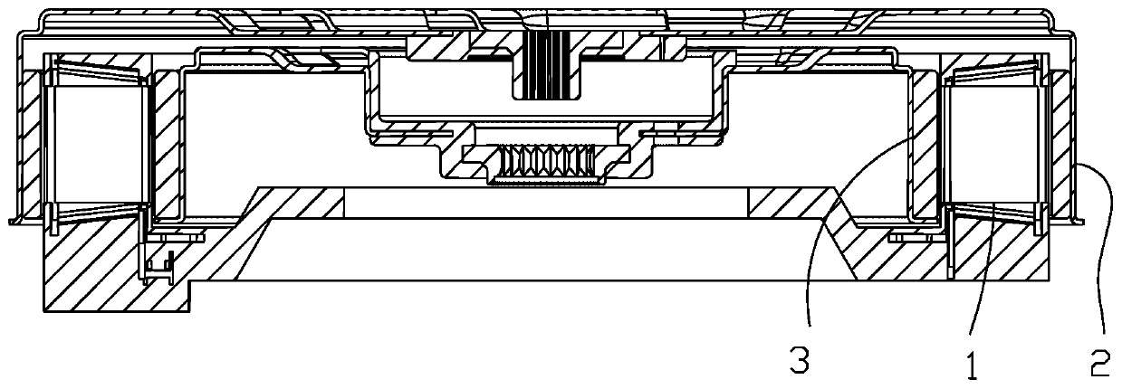
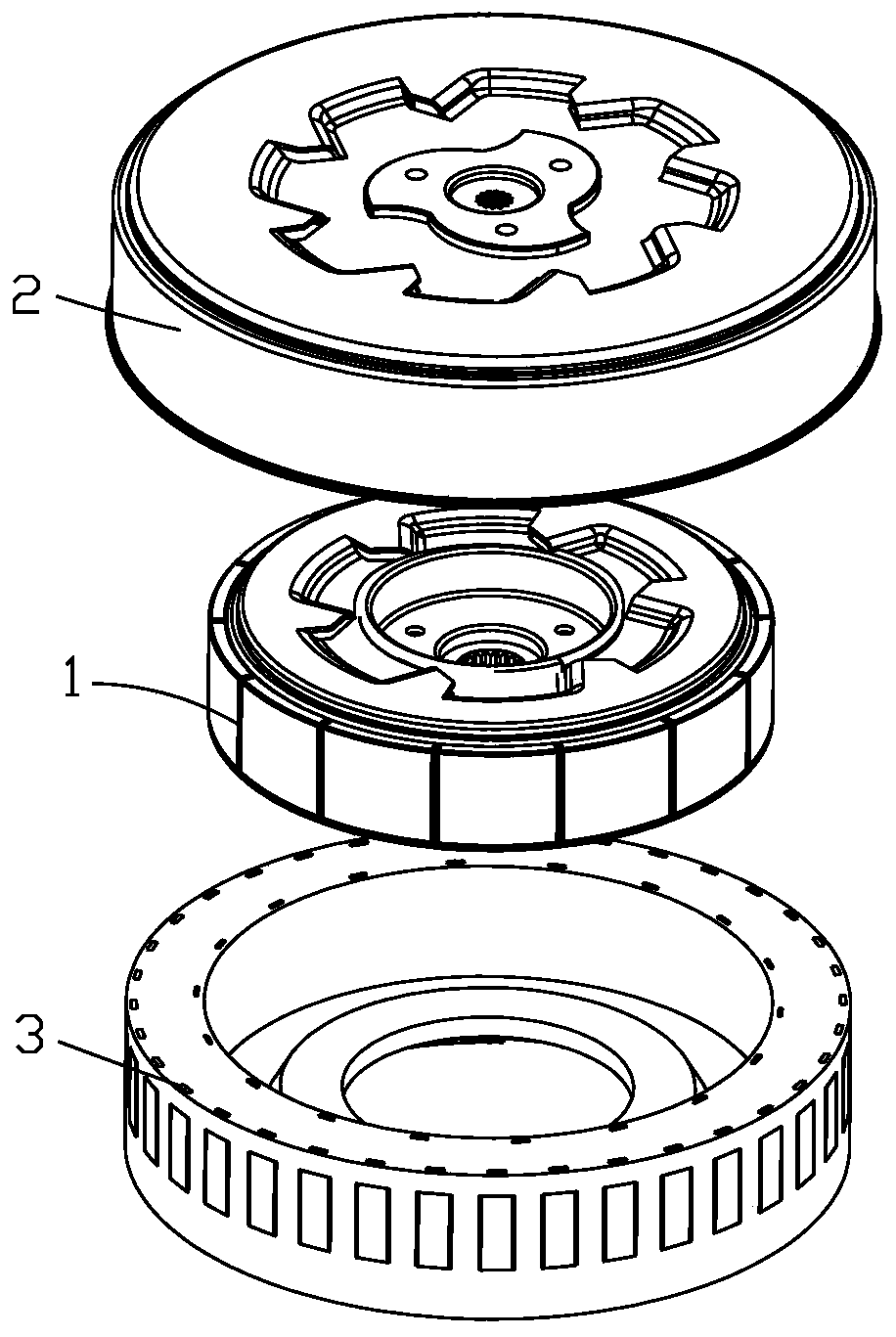
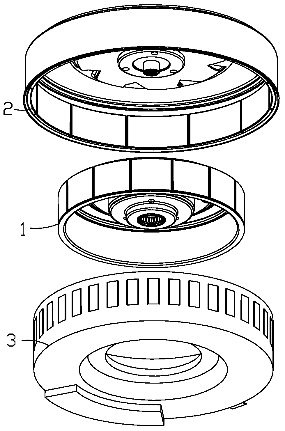
[0033] Examples. Double rotor motors, such as Figure 1 to Figure 3 As shown, it includes a stator 1, an outer rotor 2 is provided on the outside of the stator 1, an outer rotor shaft (not shown in the figure) is provided on the outer rotor 2, an inner rotor 3 is provided on the inner side of the stator 1, and an inner rotor shaft is provided on the inner rotor 3 (Not shown in the picture).
[0034] Such as Figure 4 As shown, the stator 1 includes a ring-shaped stator outer frame 10, and a plurality of circumferentially distributed first magnetic poles 11 are provided in the stator outer frame 10.
[0035] Such as Figure 5 As shown, there are thirty-six first magnetic poles 11, the first magnetic pole 11 includes a coil 111 and an I-shaped iron core 110; the stator outer frame 10 is a hollow structure, and the stator outer frame 10 A ring-shaped stator inner frame 12 is provided inside, and a plurality of magnetic pole fixing parts 120 are provided on the outer side of the stator inner frame 12. The bottom of the stator outer frame 10 is provided with a first connecting portion 101 extending horizontally inward. The first connecting portion 101 is ring-shaped, and the inner side of the first connecting portion 101 bulges upward to form a first recess 102.
[0036] Such as Image 6 As shown, the iron core 110 is embedded in the magnetic pole fixing portion 120, the magnetic pole fixing portion 120 is in the shape of a square tube, and both ends of the iron core 110 extend outward and respectively pass through the magnetic pole fixing portion 120. The iron core 110 is I-shaped, the vertical arm of the iron core lies in the magnetic pole fixing part 120, and the two transverse arms are respectively inside and outside the magnetic pole fixing part 120. The coil 111 is wound on the magnetic pole fixing part 120, and the outer side of the coil 111 is provided with the magnetic pole The baffle 121 connected to the fixed part 120 is used to prevent the coil 111 from falling off.
[0037] Such as Figure 7 with Figure 8 As shown, the outer rotor 2 includes a first cover plate 20 located above the stator outer frame 10, the outer edge of the first cover plate 20 is provided with a first flange 21 extending downward, and the first flange 21 is located outside the stator. On the outside of the frame 10, a second magnetic pole 22 is provided between the first flange 21 and the stator outer frame 10, and the second magnetic pole 22 is fixed to the inner side wall of the first flange 21.
[0038] The material of the second magnetic pole 22 is a permanent magnet, the second magnetic pole 22 is arcuate, the number of the second magnetic pole 22 is twelve, and each second magnetic pole 22 corresponds to four first magnetic poles 11.
[0039] The middle portion of the first cover plate 20 is recessed downward to form a second recessed portion 201, a first ventilation hole 202 is provided between the second recessed portion 201 and the first cover plate 20, and a positioning hole is provided on the second recessed portion 201 , The positioning hole is provided with a positioning block 24, the top of the positioning block 24 is provided with a connecting plate 25 connected to the top surface of the second recess 201, the connecting plate 25 is penetrated by the outer rotor shaft, and the bottom of the positioning block 24 extends outward A second connecting portion 204 is formed, and the second connecting portion 204 is fixed to the bottom surface of the second recessed portion 201, and the top surface of the positioning block 24 is embedded with a first adjusting block 23. There is a pattern between the first adjusting block 23 and the positioning block 24. The lower end of the first adjusting block 23 is provided with an extension 231 that passes through the positioning block 24. The first adjusting block 23 is provided with a first shaft hole 230 through which the outer rotor shaft passes. The first adjusting block 23 is connected to the outer rotor shaft. Spline connection between rotor shafts.
[0040] Such as Picture 9 with Picture 10 As shown, the inner rotor 3 includes a second cover plate 30 located between the first cover plate 20 and the stator outer frame 10. The outer edge of the second cover plate 30 extends downward to form a second flange 300. The side 300 is located inside the stator outer frame 10, a third magnetic pole 31 is provided between the second flange 300 and the stator outer frame 10, and the third magnetic pole 31 is fixed to the outer side wall of the second flange 300.
[0041] The material of the third magnetic pole 31 is a permanent magnet, the third magnetic pole 31 is arcuate, there are fourteen third magnetic poles 31, and each third magnetic pole 31 corresponds to three first magnetic poles 11.
[0042] The middle portion of the second cover plate 30 is recessed downward to form a third recessed portion 301, the connection between the third recessed portion 301 and the second cover plate 30 is provided with a second ventilation hole 302, and the inner side of the third recessed portion 301 is provided The fourth recessed portion 303, the fourth recessed portion 303 is provided with an adapter sleeve 32, the top surface of the adapter sleeve 32 is embedded with a second adjustment block 33, and the second adjustment block 33 is provided with the inner rotor shaft passing through The second shaft hole 330, the second adjusting block 33 and the inner rotor shaft are splined.
[0043] Such as Picture 11 As shown, each of the aforementioned second magnetic poles 22 corresponds to four first magnetic poles 11, which means that there are two first magnetic poles 11 completely within the wrap angle range of the arcuate second magnetic pole 22, and there are two other second magnetic poles. One magnetic pole part lies within the wrap angle range of the arc-shaped second magnetic pole 22, and each second magnetic pole 22 is affected by the magnetic fields of the four first magnetic poles 11. Each third magnetic pole 31 corresponds to three first magnetic poles 11, which means that there are three first magnetic poles 11 passing through the wrap angle range of the third magnetic pole 31, and each third magnetic pole 31 is affected by the magnetic field of the three first magnetic poles 11.
[0044] Such as Figure 13 Shown. The current wiring method of the motor is usually powered by a three-phase power supply. It is a group of three adjacent energized magnetic poles. The three magnetic poles in the same group are respectively connected to the three live wires of the three-phase power supply. The magnetic poles are all connected to the neutral line; Figure 13 The number in only indicates the Nth magnetic pole. Since the three magnetic poles are a group, the drawing method is omitted in the figure and only the first magnetic pole number in this group is drawn. Such as Picture 12 As shown, the present invention uses two three-phase power supplies, and the spaced groups use a three-phase power supply in parallel, and the three first magnetic poles in the group are respectively connected to the three live wires of the corresponding three-phase power supply, and the corresponding neutral wires are connected at the same time.
[0045] The installation method of the present invention in the washing machine: the first cover 20, the adapter sleeve 32 and the first connecting part 101 are used for fixing with the base of the washing machine, the outer rotor shaft is fixed with the outer tub of the washing machine, and the inner rotor shaft is fixed with the wave of the washing machine. The wheel is fixed.