Supercharge Your Innovation With Domain-Expert AI Agents!

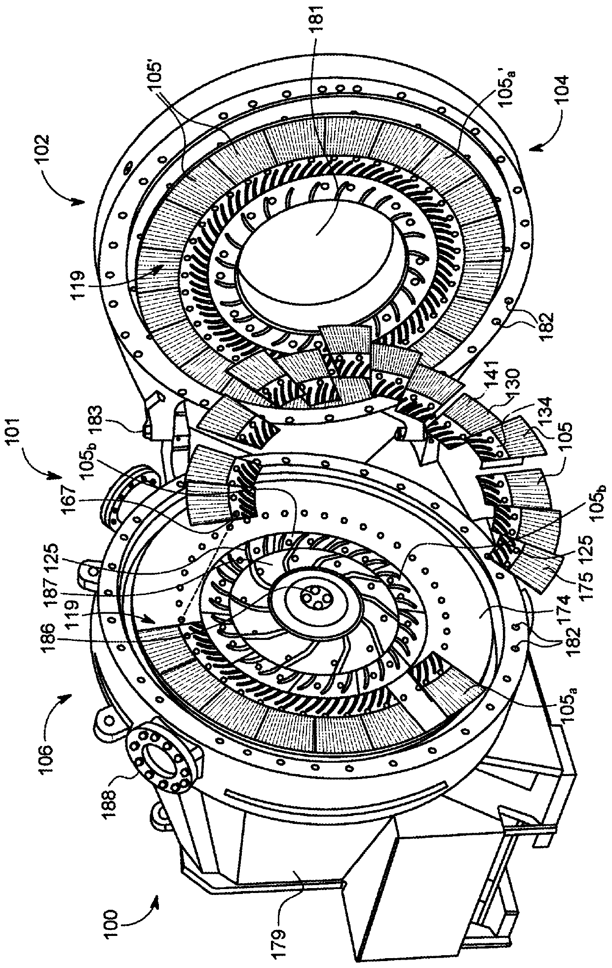
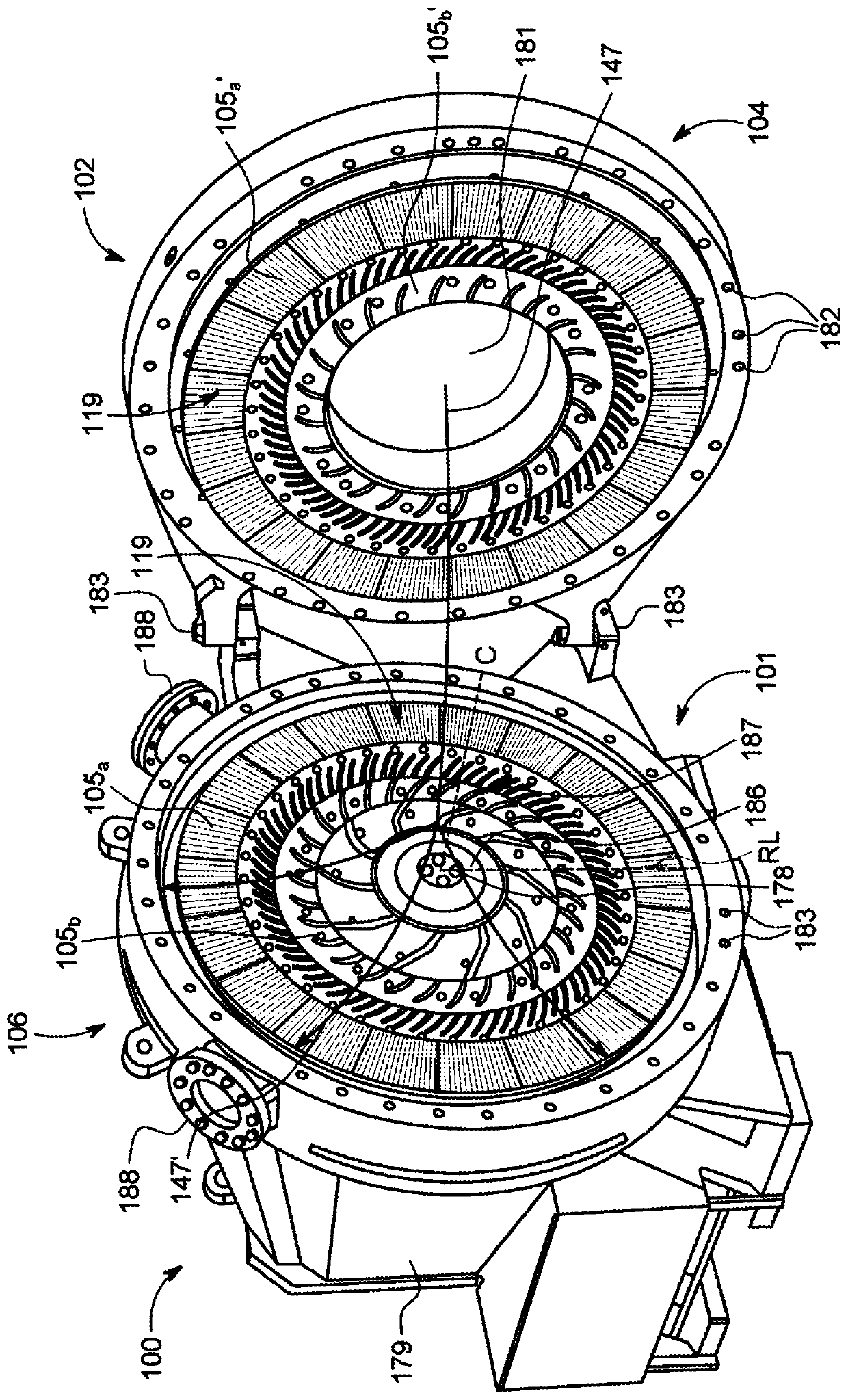
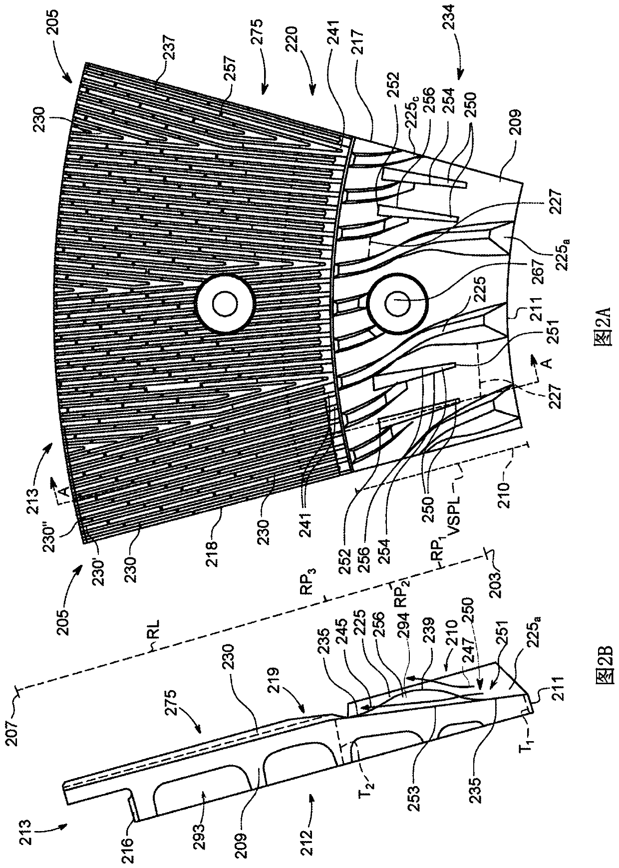
Water relief groove to prevent cavitation of opposite refiner plate

一种精磨机、磨机的技术,应用在纸浆打浆/精浆方法、纺织品和造纸、造纸等方向,能够解决精磨机板节段使用寿命减少等问题

Active Publication Date: 2020-07-24
ANDRITZ AG
View PDF8 Cites 0 Cited by
  • Summary
  • Abstract
  • Description
  • Claims
  • Application Information

AI Technical Summary

Problems solved by technology

This problem leads to a significant reduction in the service life of the refiner plate segments

Method used


Image

  • Water relief groove to prevent cavitation of opposite refiner plate
  • Water relief groove to prevent cavitation of opposite refiner plate
  • Water relief groove to prevent cavitation of opposite refiner plate

Examples


Embodiment Construction

[0034] The following detailed description of the preferred embodiments is presented for purposes of illustration and description only, and is not intended to be exhaustive or to limit the scope and spirit of the invention. The embodiment was chosen and described in order to best explain the principles of the invention and its practical application. Those of ordinary skill in the art will recognize that many changes can be made to the invention disclosed in the specification without departing from the scope and spirit of the invention.

[0035]Unless otherwise indicated, like reference numerals indicate corresponding parts throughout the several views. Although the drawings represent embodiments of various features and components according to the present disclosure, the drawings are not necessarily to scale and some features may be exaggerated to better illustrate embodiments of the present disclosure, and such illustrations should not be construed as limiting the scope of the...


PUM


Abstract

This disclosure relates to a refiner plate segment, mechanical refiners, and methods to manufacture a refiner plate segment having one or more water channels disposed in a variable substrate profile along the radial length of a refiner plate segment base and disposed between the refiner plate segment inlet and the primary refining section, wherein the variable substrate profile comprises an undulating curve configured to complement a second undulating curve on an opposing refiner plate, and wherein dimensions of the one or more water channels are sufficiently narrow to prevent wood chips fromentering the water channels and sufficiently wide to provide a bypass path for the free water.

Description

[0001] related application [0002] This application claims the benefit under 35 U.S.C. §119(e) of the earlier filing date of U.S. Provisional Patent Application No. 62 / 599,127, filed December 15, 2017, the entire contents of which are hereby incorporated by reference. technical field [0003] The present disclosure relates generally to refiners for lignocellulosic material, and more particularly to refiner plate segments for refiners. Background technique [0004] Mechanical pulp refiners usually separate, develop and cut lignocellulosic materials into fibers to impart certain mechanical and physical properties to the fibers, suitable for pulp, paper, cardboard, construction materials, packaging materials, liquid-absorbent filling materials and other products. [0005] Mechanical refiners typically include two or more opposing refiner assemblies. Each component has a raised finishing rib pattern on the refining side. Grooves separate adjacent refining edges. Typically, ...

Claims


Application Information

Patent Timeline
Patent Type & Authority Applications(China)
IPC IPC(8): D21D1/00D21D1/30
CPCB02C7/12D21D1/306D21D1/00
Inventor 马克·伯格卢克·金格拉斯
Owner ANDRITZ AG
Features
  • R&D
  • Intellectual Property
  • Life Sciences
  • Materials
  • Tech Scout
  • Unparalleled Data Quality
  • Higher Quality Content
  • 60% Fewer Hallucinations
Learn More