
Automatic feeding device

An automatic feeding and equipment technology, applied in the direction of unloading device, vibrating conveyor, conveyor control device, etc., can solve the problem of damaged and broken product parts, inability to transport ceramic parts, reduce product part feeding efficiency, product assembly efficiency, etc. problem, achieve the effect of improving the conveying efficiency and slowing down the collision

Pending Publication Date: 2020-07-31
TYCO ELECTRONICS (SHANGHAI) CO LTD +1
View PDF0 Cites 6 Cited by
  • Summary
  • Abstract
  • Description
  • Claims
  • Application Information

AI Technical Summary

Problems solved by technology

Some product parts are made of brittle materials, for example, ceramic parts made of ceramic materials, if there is a collision during transportation, the product parts will be damaged and cracked
Therefore, the existing automatic feeding equipment cannot transport ceramic parts, and currently only manual feeding can be used. Workers need to clamp the ceramic parts to the predetermined assembly position one by one through clamps, which reduces the feeding efficiency of product parts and product quality. Assembly efficiency

Method used


Image

  • Automatic feeding device

Examples


Embodiment Construction

[0020] The technical solutions of the present invention will be further specifically described below through the embodiments and in conjunction with the accompanying drawings. In the specification, the same or similar reference numerals designate the same or similar components. The following description of the embodiments of the present invention with reference to the accompanying drawings is intended to explain the general inventive concept of the present invention, but should not be construed as a limitation of the present invention.

[0021] In addition, in the following detailed description, for purposes of explanation, numerous specific details are set forth in order to provide a comprehensive understanding of the embodiments of the present disclosure. It may be evident, however, that one or more embodiments may be practiced without these specific details. In other instances, well-known structures and devices are shown in diagrammatic form to simplify the drawings.

[0...


PUM


Abstract

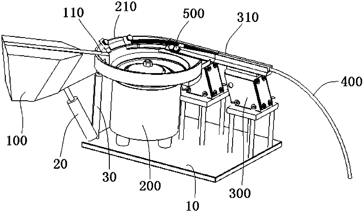
The invention discloses an automatic feeding device. The automatic feeding device comprises a hopper and a circular vibration supply device, wherein the hopper is used for accommodating product components to be supplied; and the circular vibration supply device comprises a vibrating disc with a spiral feeding track, the hopper is adapted to pour the product components contained in the vibrating disc, and the circular vibration supply device is adapted to drive the product part contained in the vibrating disc to be conveyed upwards along the spiral track by vibration. The automatic feeding device further includes a supporting part and a driver, the hopper is rotatably mounted on the supporting part, and the driver is used for driving the hopper to rotate, so that the speed of rotation of the hopper and the feeding speed of the hopper can be controlled by the driver, it is ensured that the product components in the hopper are delivered to the vibrating disc at a predetermined speed, andthe product components conveyed into the vibrating disc are prevented from colliding with each other. Accordingly, the automatic feeding device is capable of transporting fragile product components, and improving the delivery efficiency of the fragile product components.

Description

technical field [0001] The invention relates to an automatic feeding device, in particular to an automatic feeding device suitable for transporting fragile product parts to a predetermined position. Background technique [0002] In the automated production of electronic product components, it is necessary to transport the product components to a predetermined assembly location. Some product parts are made of brittle materials, for example, ceramic parts made of ceramic materials, if there is a collision during transportation, the product parts will be damaged and cracked. Therefore, the existing automatic feeding equipment cannot transport ceramic parts, and currently only manual feeding can be used. Workers need to clamp the ceramic parts to the predetermined assembly position one by one through clamps, which reduces the feeding efficiency of product parts and product quality. Assembly efficiency. Contents of the invention [0003] The purpose of the present invention i...

Claims


Application Information

Patent Timeline
Patent Type & Authority Applications(China)
IPC IPC(8): B65G47/14B65G27/02B65G27/04B65G43/08B65G49/08
CPCB65G47/1428B65G27/02B65G27/04B65G43/08B65G49/08B65G2207/28
Inventor 王长军张丹丹鲁异刘洪涛
Owner TYCO ELECTRONICS (SHANGHAI) CO LTD
Learn More