Driving circuit and display device
A technology for driving circuits and display devices, which is applied to static indicators, instruments, etc., can solve the problem that the display device cannot meet the refresh rate and other problems, and achieve the requirements of improving the picture display quality, the best visual experience, and the low power consumption of the low refresh rate. Effect
- Summary
- Abstract
- Description
- Claims
- Application Information
AI Technical Summary
Problems solved by technology
Method used
Image

Examples
Embodiment 1
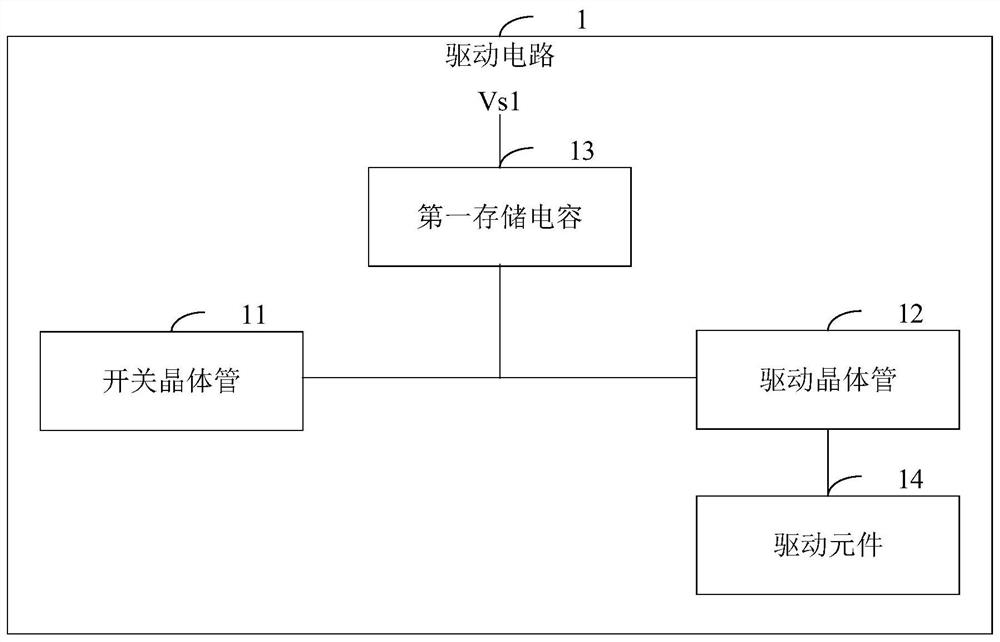
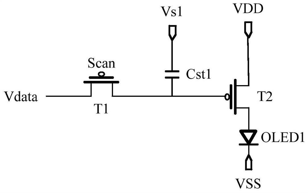
[0057] In embodiment one, if figure 2 As shown, when the driving circuit 1 is a 2T1C driving circuit 1, the switch transistor 11 includes: a first transistor T1. The driving transistor 12 includes: a second transistor T2. The first storage capacitor 13 includes: a first capacitor Cst1. The driving element 14 includes: a first light emitting diode OLED1.
[0058]The first pole of the first transistor T1 is electrically connected to the source signal terminal Source, the gate of the first transistor T1 is electrically connected to the gate signal terminal Gate, and the second pole of the first transistor T1 is respectively connected to the first electrode of the first capacitor Cst1. terminal is electrically connected to the gate of the second transistor T2, the first pole of the second transistor T2 is electrically connected to the positive voltage signal terminal VDD of the power supply, the second pole of the second transistor T2 is electrically connected to the anode of t...
Embodiment 2
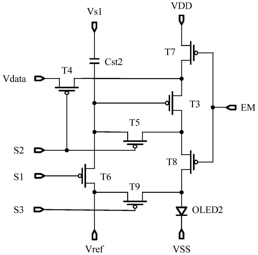
[0063] In the second embodiment, if image 3 As shown, when the driving circuit 1 is a 7T1C driving circuit 1, the switching transistor 11 and the driving transistor 12 include: the third transistor T3, the fourth transistor T4, the fifth transistor T5, the sixth transistor T6, the seventh transistor T7, the Eight transistor T8 and ninth transistor T9. The first storage capacitor 13 includes: a second capacitor Cst2. The driving element 14 includes: a second light emitting diode OLED2.
[0064] The gate of the third transistor T3 is electrically connected to the first terminal of the second capacitor Cst2, the first pole of the fifth transistor T5, and the first pole of the sixth transistor T6, respectively, and the first pole of the third transistor T3 is connected to the first pole of the fourth transistor T3 respectively. The first pole of the transistor T4 is electrically connected to the first pole of the seventh transistor T7, and the second pole of the third transisto...
Embodiment 3
[0076] In the third embodiment, in figure 2 Based on the example shown, as Image 6 As shown, the second storage capacitor 15 includes: a third capacitor Cst3. A first terminal of the third capacitor Cst3 is electrically connected to the gate of the second transistor T2, and a second terminal of the third capacitor Cst3 is electrically connected to the positive voltage signal terminal VDD of the power supply.
[0077]Based on the above connection relationship, the gate of the first transistor T1 is connected to the signal input from the gate signal terminal Gate, so that the first transistor T1 is turned on, and the signal input from the source signal terminal Source enters the first capacitor through the first transistor T1 The first terminal of Cst1, the first terminal of the third capacitor Cst3 and the gate of the second transistor T2, and under different refresh frequencies of the display device, the second terminal of the first capacitor Cst1 is connected to the first ...
PUM
 Abstract
Description
Claims
Application Information
 - R&D Engineer
- R&D Manager
- IP Professional
- Industry Leading Data Capabilities
- Powerful AI technology
- Patent DNA Extraction
Browse by: Latest US Patents, China's latest patents, Technical Efficacy Thesaurus, Application Domain, Technology Topic.
© 2024 PatSnap. All rights reserved.Legal|Privacy policy|Modern Slavery Act Transparency Statement|Sitemap