Drain valve for a sanitary cistern

A technology of drain valve and water tank, applied in flushing equipment with water tank, lift valve, valve details, etc., can solve the problem of no control device, etc., and achieve the effect of high flushing efficiency and reliable orientation

Active Publication Date: 2020-08-07
VIEGA TECH GMBH & CO KG
View PDF7 Cites 0 Cited by
  • Summary
  • Abstract
  • Description
  • Claims
  • Application Information

AI Technical Summary

Problems solved by technology

[0006] In the concealed cistern known from DE 20 2007 017 789 U1 no mechanical actuating device is provided for triggering the flushing

Method used


Image

  • Drain valve for a sanitary cistern
  • Drain valve for a sanitary cistern
  • Drain valve for a sanitary cistern

Examples


Embodiment Construction

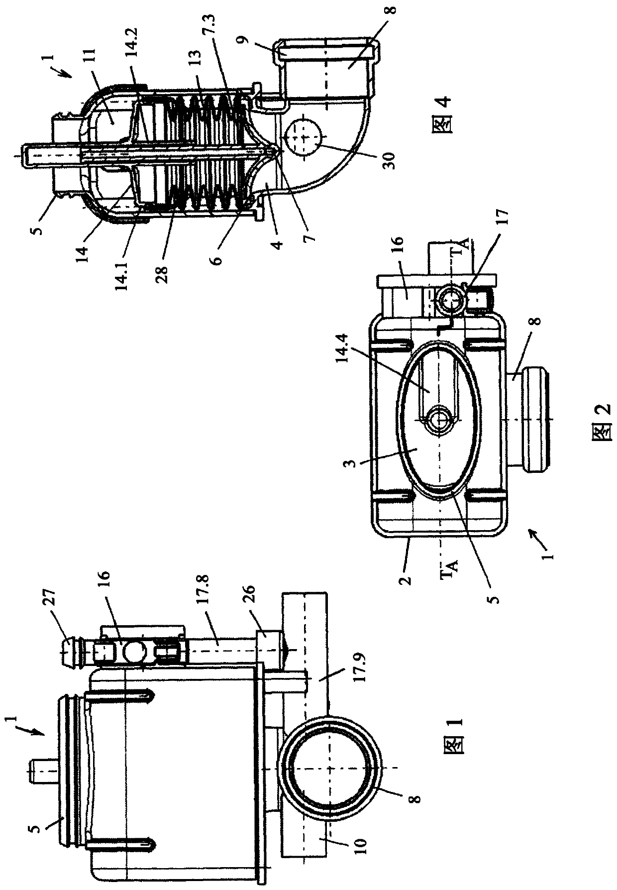
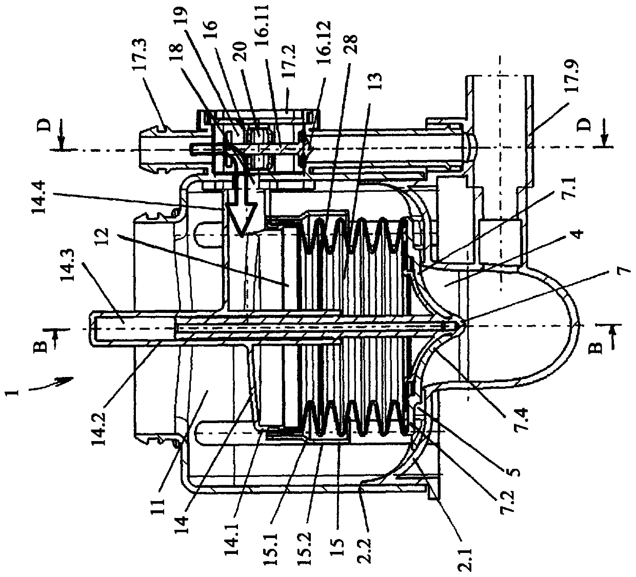
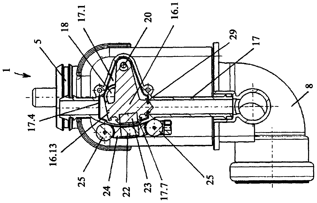
[0037] The drain valve 1 shown in the figures is designed for combination with a sanitary water tank (not shown), especially a concealed water tank. Conventional drain valves for sanitary water tanks are located inside the tank and are accessible for maintenance or repair purposes through inspection ports provided above the toilet or urinal.

[0038] In contrast, the drain valve 1 according to the invention is designed such that, in the assembled state, it is arranged below the water tank and thus outside the water tank. Therefore, the drain valve 1 realizes that the inspection port arranged above the toilet or the urinal in the traditional concealed water tank is moved to a position behind the toilet or the urinal, so that the inspection port is completely covered by the toilet or the urinal.

[0039] The drain valve 1 has a closed valve housing (drain valve housing) 2 which is provided with an inlet 3 and an outlet 4 . The inlet 3 is delimited by a connecting piece 5 which ...


PUM


Abstract

The invention relates to a drain valve for a sanitary cistern, in particular a concealed cistern, having a valve housing (2) with a drain opening (4), the drain opening (4) being delimited by a valveseat (6), and a valve body (7), which rests in a sealing manner on the valve seat (6) when the drain valve is closed, the valve housing (2) having a housing chamber (11), arranged upstream of the valve seat (6) in the direction of flow, for receiving water. To allow the drain valve to be arranged outside the cistern and to enable access to the drain valve for maintenance or removal via an inspection opening that can be concealed by a toilet bowl or urinal bowl, according to the invention the valve body (7) is provided with an auxiliary chamber (12) for receiving water, the water receiving volume of which, when the drain valve (1) is open, is smaller than when the drain valve (1) is closed, the auxiliary chamber (12) being delimited by a flexible and / or moveable wall section, and an auxiliary drain valve (16) being associated with the auxiliary chamber (12), which auxiliary drain valve, when in a first position, permits water to flow into the auxiliary chamber (12), and, when in a second position, permits water to flow out of the auxiliary chamber (12).

Description

technical field [0001] The invention relates to a drain valve for a sanitary flush tank, in particular a concealed tank, comprising: a valve housing with a drain opening, wherein the drain opening is delimited by a valve seat; and sealingly sealed in the closed state of the drain valve A valve body placed on the valve seat, wherein the valve housing has a housing chamber for receiving water arranged upstream of the valve seat in the outflow direction. Background technique [0002] Cisterns for toilets or urinals are known in various embodiments. Conventional sanitary water tanks, in particular concealed water tanks, have a tank in which inspection openings are formed in the front wall or top side. Functions such as drain and fill valves are installed in the tank through inspection ports. The inspection opening is usually combined with an operating panel which has one or two movably mounted operating buttons for triggering the flushing. The inspection hatch enables access ...

Claims


Application Information

Patent Timeline
Patent Type & Authority Applications(China)
IPC IPC(8): E03D3/10E03D1/14E03D1/34F16K31/08
CPCE03D3/10E03D1/14E03D1/34F16K31/088F16K1/126F16K31/385
Inventor 约翰内斯·阿恩特格哈德·罗特施泰因海因茨-沃纳·维塞尔
Owner VIEGA TECH GMBH & CO KG
Why Eureka
Try Eureka