Check patentability & draft patents in minutes with Patsnap Eureka AI!

Heated inlet of a crankcase ventilation system

A crankcase ventilation, crankcase technology, applied in the crankcase field, can solve problems such as inability to obtain efficiency, not properly solved, etc.

Pending Publication Date: 2020-08-11
CATERPILLAR INC
View PDF1 Cites 0 Cited by
  • Summary
  • Abstract
  • Description
  • Claims
  • Application Information

AI Technical Summary

Problems solved by technology

However, the ventilation system of the '265 Proclamation may not properly address components in the fuel (e.g., sulfur) that may form harmful

Method used


Image

  • Heated inlet of a crankcase ventilation system
  • Heated inlet of a crankcase ventilation system
  • Heated inlet of a crankcase ventilation system

Examples


Embodiment Construction

[0013] Both the foregoing general description and the following detailed description are exemplary and explanatory only and do not limit the features that are claimed. As used herein, the terms "comprise", "comprising", "having", "including" or variations thereof are intended to cover a non-exclusive inclusion such that a process comprising a list of elements A method, article, or apparatus includes not only those elements, but may include other elements not expressly listed or inherent to such a process, method, article, or apparatus. Additionally, relative terms such as, for example, "about," "substantially," "substantially," and "approximately" are used to indicate a possible variation of ±10% of the stated value.

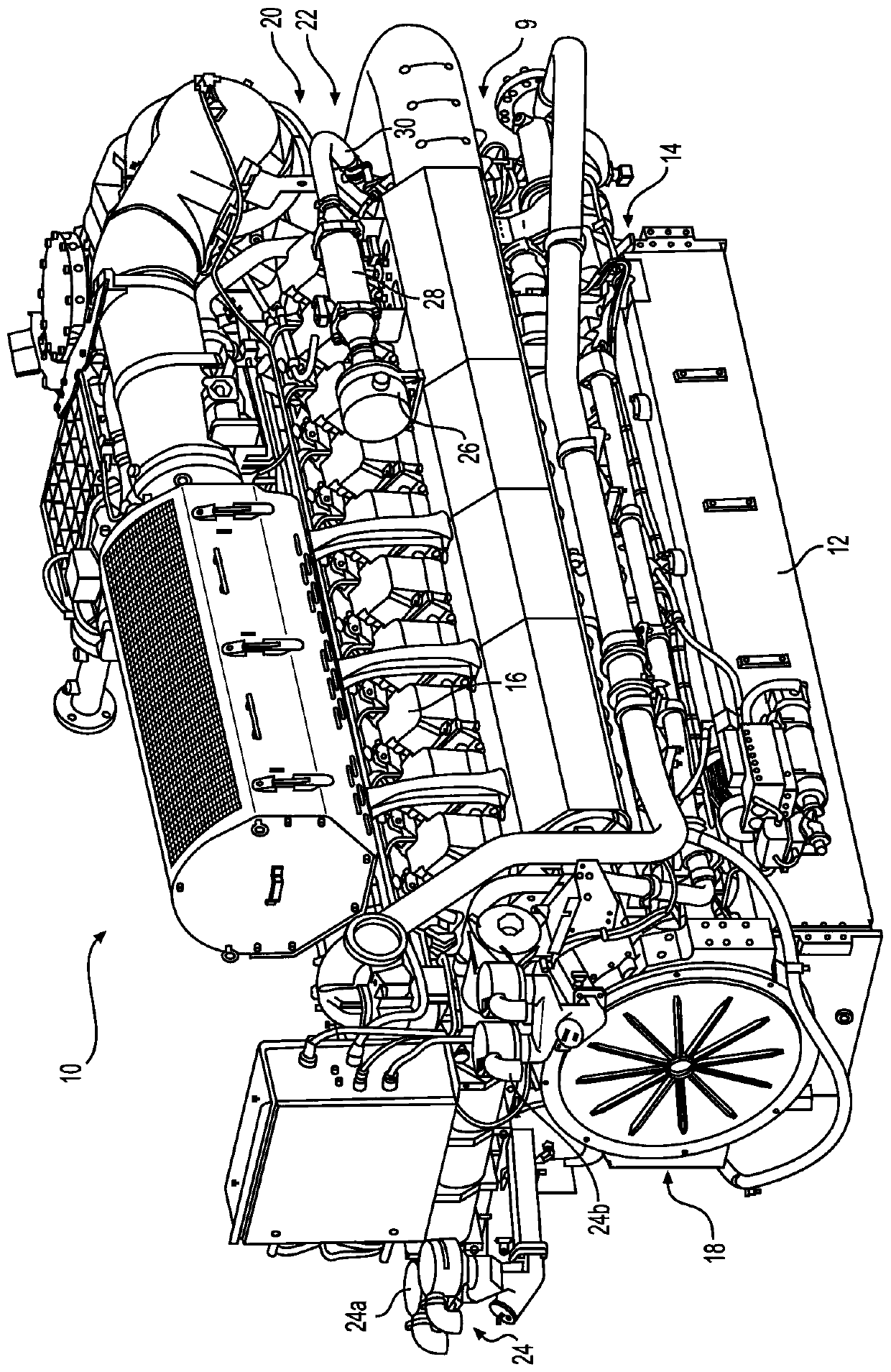
[0014] figure 1 is a perspective view of an internal combustion engine 10 having an exemplary crankcase ventilation system 20 according to aspects of the present disclosure. Engine 10 may be a stationary engine. As used herein, a "stationary engine" may be an...


PUM


Abstract

The invention relates to a heated inlet of a crankcase ventilation system. A method for ventilating a crankcase of an internal combustion engine using natural gas as a fuel source may include filtering ambient air through an air filter. The method may also include heating the filtered ambient air by a jacket heat exchanger. The method may further include directing the heated ambient air through aninlet of the crankcase to purge blow-by gases including natural gas from the crankcase.

Description

technical field [0001] The present disclosure relates generally to crankcases for internal combustion engines, and more particularly to heated inlets for crankcase ventilation systems for such internal combustion engines. Background technique [0002] Internal combustion engines typically include a crankcase to provide a housing for the engine's crankshaft. During operation of the engine, blow-by gases (eg, gaseous fuel, air, and / or combustion gases) may leak into the crankcase. Blow-by gases can contaminate an engine's oil lubrication system, can pressurize the crankcase, and can affect overall engine emissions. Additionally, if the engine is fueled with a gaseous fuel (eg, natural gas or landfill gas), the blow-by gas may include corrosive fumes such as sulfur. The crankcase may include a ventilation system, such as an inlet / outlet breather system, to assist in purging blow-by gases from the crankcase with fresh ambient air. When the engine is used in a cold environment...

Claims


Application Information

Patent Timeline
IPC IPC(8): F01M13/00F01M13/02F02M31/10F02M35/04
CPCF01M13/00F01M13/028F01M2013/0038F02M31/042F02M31/10F02M35/042F01M13/0033F01P3/20F02B2043/103F28D7/1607F28D2021/0026F01P2060/18F02B43/12F28D2021/004
Inventor L·D·克雷斯R·A·劳伦斯W·詹金斯
Owner CATERPILLAR INC
Features
  • R&D
  • Intellectual Property
  • Life Sciences
  • Materials
  • Tech Scout
  • Unparalleled Data Quality
  • Higher Quality Content
  • 60% Fewer Hallucinations
Learn More